Appendix J: 4-20 mA Input and Output
Page J-6 Lasair II Particle Counter Operations Manual
4-20 mA Output Connector Wiring and Channel Definitions
The connector is labeled with pin 1 and pin 16.
4–20 mA Out Status Channel
Channel 1 can be used to monitor the following information:
• Power On/Off
• Sampling/Idle
• Laser Error
• Pump Error
• Particle Alarm
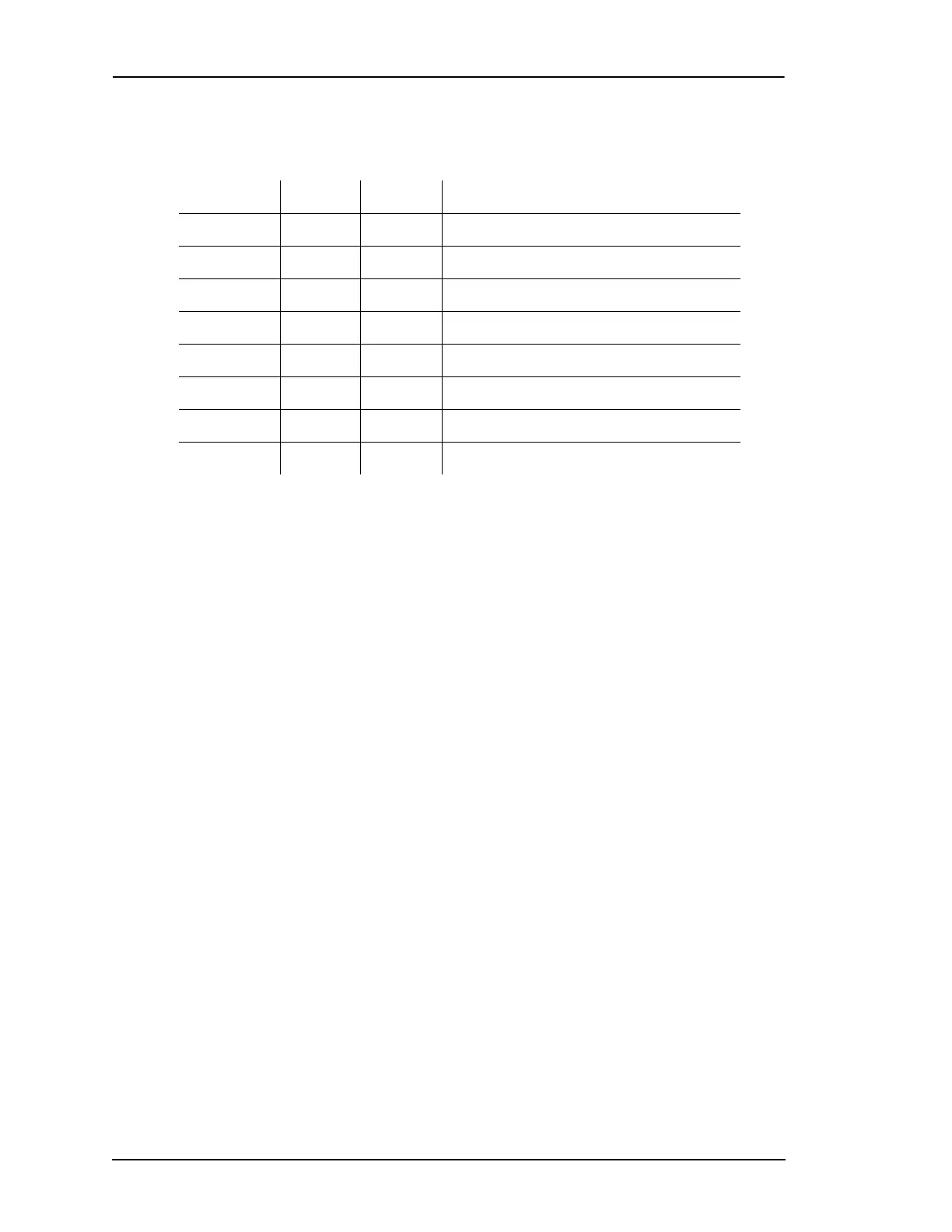
Table J-2: 4-20 mA Output
Channel Output Return Definition
Channel 1 1 2 Status and alarm information
Channel 2 3 4 Manifold position
Channel 3 5 6 Particle channel 1 (smallest size)
Channel 4 7 8 Particle channel 2
Channel 5 9 10 Particle channel 3
Channel 6 11 12 Particle channel 4
Channel 7 13 14 Particle channel 5
Channel 8 15 16 Particle channel 6 (largest size)
Connector Type: Molex® 43025-1600
Terminal Pins: Molex 43030-0007
Wiring Gauge: 20–24 AWG
Hand-held crimping tool
a
:
a. For details about how to produce a good crimp with this
tool, see www.molex.tool.
Molex Part No. 63811-2800
 Loading...