Mounted to the spindle assembly is a ring with equally spaced notches and one additional
notch spaced midway between two of the other notches; this is referred to as the Phase
Lock Ring and is used for sectoring
and
speed control.
In
dual disk models, a fixed disk is mounted to the spindle assembly; it is referred to
as
the lower disk but is not removable
in
the same manner
as
the cartridge. The second
disk is contained within the removable cartridge and is driven by a magnetic clutch which
is located
on
top
of
the spindle assembly. A precision ground cone
on
the
end
of
the
spindle suitably locates the hub
of
the disk which is mounted in the cartridge. Rotary
motion is imparted to both disks simultaneously.
The
blower is rotated while the drive motor is running and the disk is spinning. Air flow
from the blower travels through the disk area and purges the air of any contaminants in
this
area.
Air is drawn
in
at the lower front part of the front
bezel
and passes through a high
efficiency absolute filter located in the lower front portion of the base assembly.
Air is ducted to the squirrel cage blower and thence to the area below the fixed disk.
Suitable vanes
on
the spindle provide additional pumping action to cause air
to
flow into
the
area
of the upper disk. Air is exhausted at the rear
of
the disk drive.
As
a function of
exhausting the air, the electronics package
Is provided with Suitable cooling.
Additional cooling is provided through convection cooling of the heatsink assemblies
mounted at the rear of the base assembly. Power transistors mounted on these heatsink
assemblies are used in the power supply regulators
and
the positioner power amplifiers.
The base assembly provides mounting attachment pOints for the rack mounting slides,
switch brackets, front bezel,
and
the supporting structure for the printed circuit boards
and dust cover.
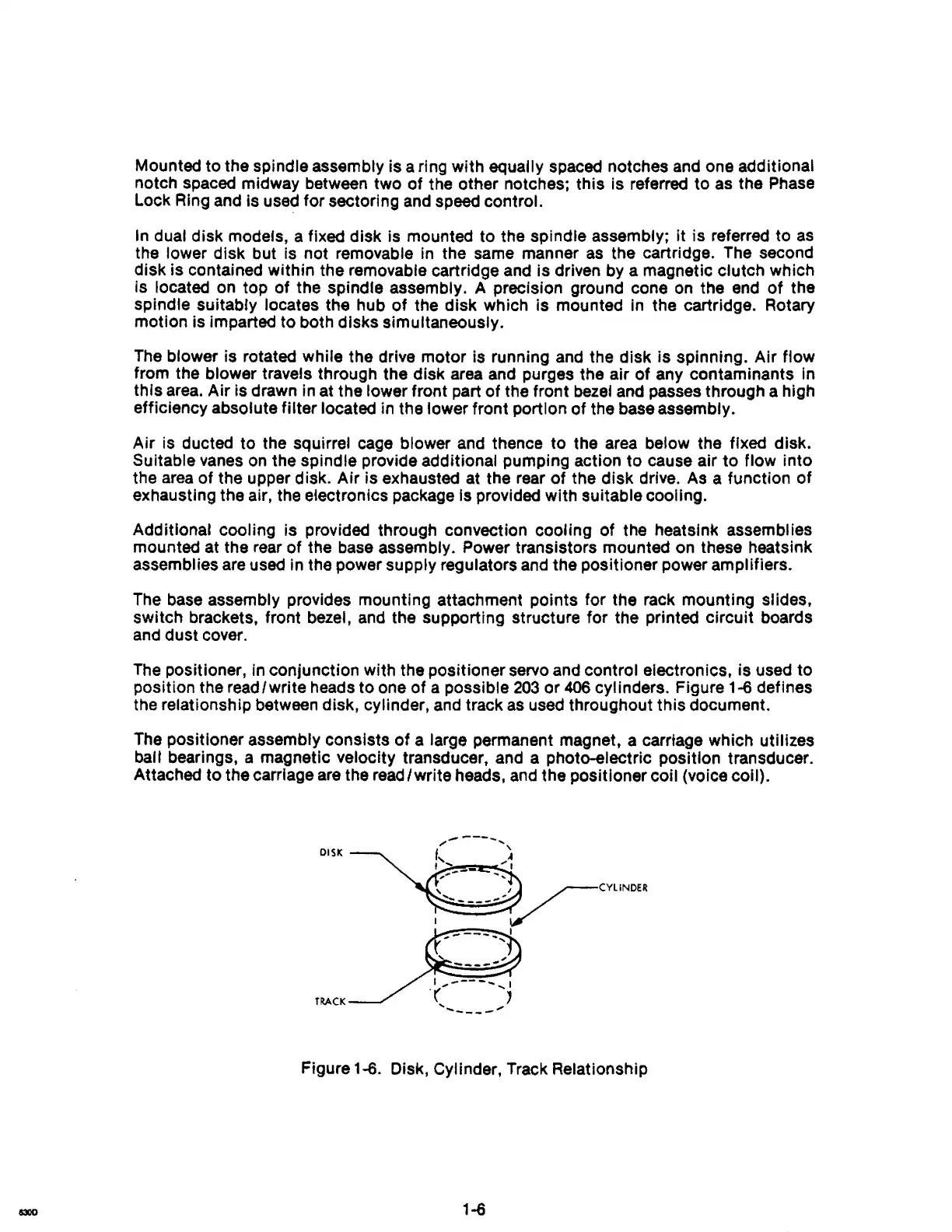
The
pOSitioner, in conjunction with the positioner servo and control electroniCS, is used to
position the read/write heads
to
one of a possible
203
or
406
cylinders. Figure 1-6 defines
the relationship between disk, cylinder, and track
as
used throughout this document.
The positioner assembly consists
of
a large permanent magnet, a carriage which utilizes
ball bearings, a magnetic velocity transducer, and a photo-electric position transducer.
Attached to the carriage
are
the read/write heads,
and
the pOSitioner coil (voice coli).
Figure 1-6. Disk, Cylinder, Track Relationship
1-6