[II
I
(11
3.
4.
5.
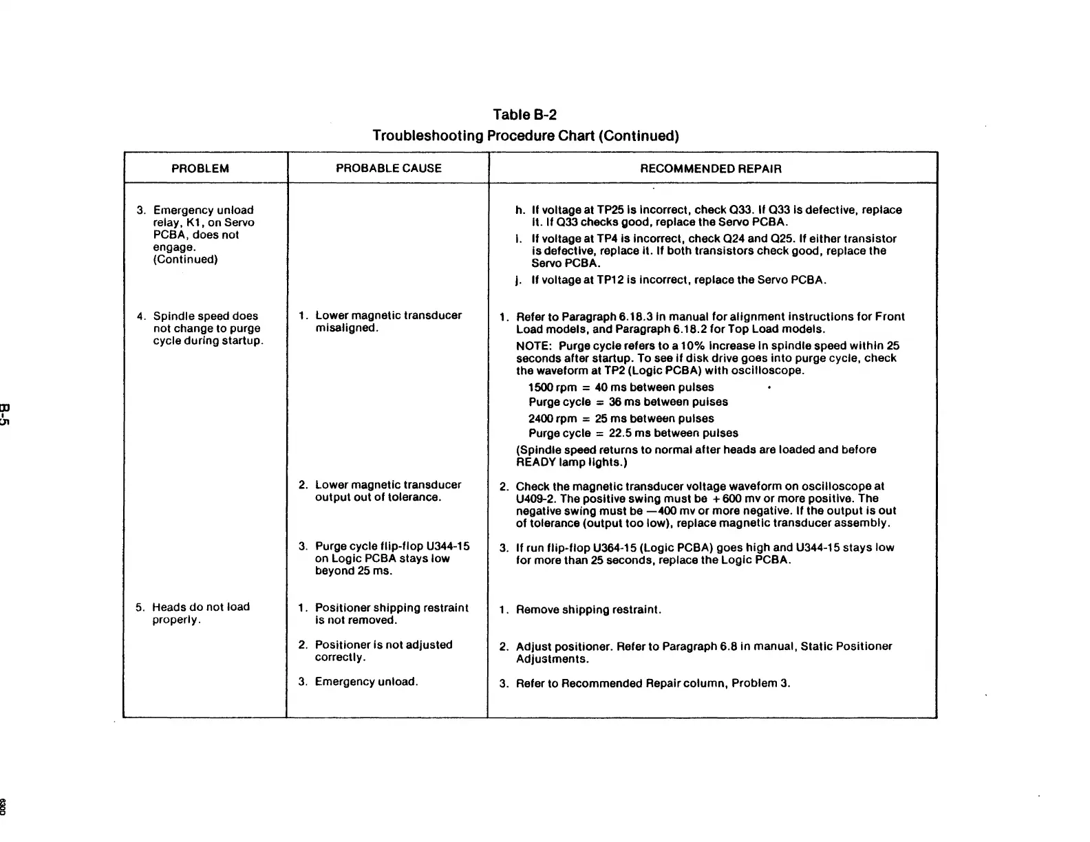
PROBLEM
Emergency unload
relay,
K1, on Servo
PCBA,
does not
engage.
(Continued)
Spindle speed does
not change to purge
cycle during startup.
Heads
do
not load
properly.
1.
2.
3.
1.
2.
3.
Table B-2
Troubleshooting Procedure Chart (Continued)
PROBABLE CAUSE
RECOMMENDED REPAIR
h.
If voltage at TP25 Is incorrect, check
033.
If Q33 is defective, replace
It. If
033
checks good, replace the Servo PCBA.
I.
If
voltage at
TP4
is
incorrect, check
024
and
025.
If either transistor
is
defective, replace it. If both transistors check good, replace the
ServoPCBA.
j.
If
voltage at TP12 is incorrect, replace the Servo PCBA.
Lower magnetic transducer
1.
Refer
to
Paragraph 6.18.3 In manual
for
alignment
instructions
for
Front
misaligned.
Load models, and Paragraph 6.18.2
for
Top Load models.
NOTE: Purge cycle refers
to
a 10% Increase In spindle speed
within
25
seconds after startup. To see
if
disk
drive goes
into
purge cycle, check
the waveform at
TP2
(Logic PCBA)
with
oscilloscope.
1500 rpm
=
40
ms between pulses
.
Purge cycle =
36
ms
between pulses
2400 rpm =
25
ms
between pulses
Purge cycle
= 22.5 ms between pulses
(Spindle speed returns
to
normal after heads are loaded and before
READY lamp
lights.)
Lower magnetic transducer
2.
Check the magnetic transducer voltage waveform on oscilloscope at
output
out
of
tolerance.
U409-2. The positive swing
must
be + 600 mv or more positive. The
negative swing
must
be
-400
mv
or
more negative.
If
the
output
is
out
of
tolerance (output
too
low), replace
magnetic
transducer assembly.
Purge cycle
flip-flop
U344-15
3.
If
run
flip-flop
U364-15 (Logic PCBA) goes
high
and U344-15 stays
low
on Logic PCBA stays
low
for more than
25
seconds, replace the
Logic
PCBA.
beyond
25
ms.
Positioner shipping restraint
1. Remove shipping restraint.
is not removed.
Positioner
is
not
adjusted
2.
Adjust
positioner. Refer
to
Paragraph 6.8
in
manual, Static Positioner
correctly.
Adjustments.
Emergency unload.
3.
Refer to Recommended Repair column, Problem
3.