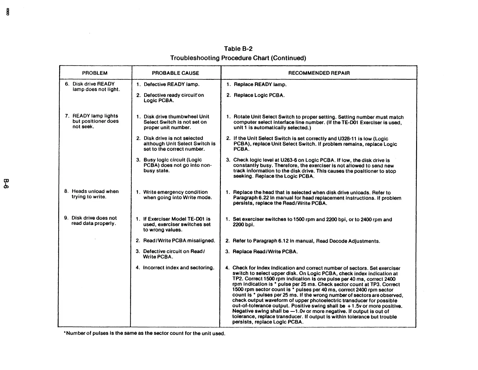
Table B-2
Troubleshooting Procedure Chart (Continued)
PROBLEM
PROBABLE CAUSE
RECOMMENDED REPAIR
6.
Disk drive
READY
1. Defective READY lamp.
1.
Replace READY lamp.
lamp does not light.
2.
Defective ready
circuiron
2.
Replace Logic PCBA.
LogicPCBA.
7.
READY lamp
lights
1.
Disk drive thumbwheel Unit
1.
Rotate Unit Select Switch to proper setting. Setting number must match
but positioner does
Select Switch Is
not
set on
computer select interface
line number. (If the TE-001 Exerciser
is
used,
not seek.
proper
unit
number.
unit
1
is
automatically selected.)
2.
Disk drive
is
not selected
2.
If the
Unit
Select Switch Is set correctly and
U328-11
Is low (Logic
although Unit
Select Switch Is
PCBA),
replace Unit Select Switch. If problem remains, replace Logic
set to the correct number.
PCBA.
3.
Busy logic
circuit
(Logic
3.
Check
logic
level at U263-6 on Logic PCBA.
If
low, the disk drive is
PCBA) does not
go
into
non-
constantly busy. Therefore, the exerciser
is
not
allowed to send new
busy state.
track information
to
the disk drive. This causes the positioner to stop
seeking. Replace the Logic
PCBA.
8.
Heads unload when
1.
Write emergency condition
1.
Replace the head that
Is selected when disk drive unloads. Refer to
trying to write.
when
gOing
into
Write mode.
Paragraph 6.22 In manual for head replacement Instructions.
if
problem
persists, replace the Read/Write
PCBA.
9.
Disk drive does not
1.
If Exerciser Model TE-001
is
1.
Set exerciser switches to 1500 rpm and
2200
bpi,
or
to
2400
rpm and
read data properly.
used, exerciser switches set
2200
bpI.
to
wrong values.
2.
Read
/ Write PCBA misaligned.
2.
Refer
to
Paragraph 6.12 In manual, Read Decode Adjustments.
3.
Defective Circuit on Read/
3.
Replace Read/Write PCBA.
WritePCBA.
4.
Incorrect index and sectoring.
4.
Check
for
Index Indication and correct number
of
sectors. Set exerciser
switch
to
select upper disk. On Logic PCBA, check index indication
at
TP2. Correct 1500 rpm indication
is
one pulse per
40
ms, correct
2400
rpm indication Is • pulse per
25
ms. Check sector count at
TP3.
Correct
1500 rpm sector count
Is • pulses per
40
ms, correct
2400
rpm sector
count
Is • pulses per
25
ms.
If
the wrong number
of
sectors are observed,
check
output
waveform
of
upper photoelectric transducer for possible
out-of-tolerance output.
Positive swing shall
be
+ 1.5v
or
more positive.
Negative swing shall be
-1.0v
or
more negative.
If
output
is
out
of
tolerance, replace transducer. If
output
is within tolerance but trouble
perSists, replace Logic PCBA .
• Number
of
pulses
is
the same
as
the sector count for the
unit
used.