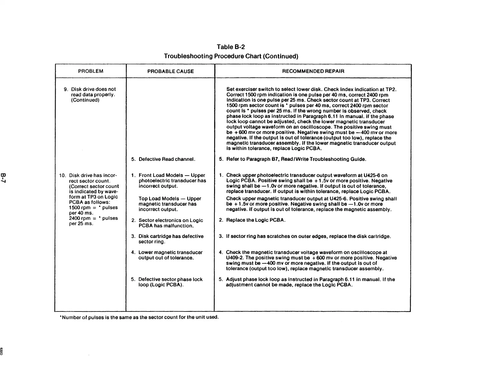
Table B-2
Troubleshooting Procedure Chart (Continued)
PROBLEM
PROBABLE CAUSE
RECOMMENDED REPAIR
9. Disk drive does not Set exerciser switch to select lower disk. Check Index Indication at TP2.
read data properly.
Correct 1500 rpm indication
is
one pulse per
40
ms, correct
2400
rpm
(Continued)
indication
Is one pulse per
25
ms. Check sector count at TP3. Correct
1500 rpm sector count
is
• pulses per 40 ms, correct 2400 rpm sector
count
15
• pulses per
25
ms.
If
the wrong number Is observed, check
phase lock loop as
Instructed in Paragraph
6.11
in
manual. If the phase
lock loop cannot
be
adjusted, check the lower magnetic transducer
output voltage waveform on
an
oscilloscope. The positive swing
must
be + 600 mv
or
more positive. Negative swing
must
be
-400
mv
or
more
negative.
If
the
output
Is
out
of
tolerance
(output
too low), replace the
magnetic transducer assembly.
If
the lower magnetic transducer
output
Is within tolerance, replace Logic PCBA.
5.
Defective
Read
channel.
5.
Refer to Paragraph B7, Read/Write Troubleshooting Guide.
10.
Disk drive has incor-
L
Front Load Models - Upper
1.
Check upper photoelectric transducer
output
waveform at U425-6 on
rect sector count.
photoelectric transducer has Logic
PCBA. Positive swing shall
be
+ 1.5v
or
more positive. Negative
(Correct sector count
incorrect output. swing shall be
-1.0v
or
more negative. If
output
Is
out
of
tolerance,
is indicated by wave-
replace transducer.
If output Is within tolerance, replace Logic PCBA.
form at
TP3
on Logic
Top Load Models - Upper Check upper magnetic transducer
output
at U425-6. Positive swing shall
PCBA
as
follows:
magnetic transducer has
be
+ 1.5v or more positive. Negative swing shall
be
-1.0v
or
more
1500 rpm = • pulses
incorrect output. negative.
If
output
is
out
of
tolerance, replace the magnetic assembly.
per
40
ms.
2400
rpm = • puises
2.
Sector electronics on Logic
2.
Replace the Logic PCBA.
per
25
ms.
PCBA has malfunction.
3.
Disk cartridge has defective
3.
If
sector ring has scratches on outer edges, replace the
disk
cartridge.
sector ring.
4.
Lower magnetic transducer
4.
Check the magnetic transducer voltage waveform on oscilloscope at
output out
of
tolerance. U409-2. The positive swing must
be
+ 600 mv
or
more positive. Negative
swing must
be
-400
mv or more negative.
If
the
output
Is
out
of
tolerance (output
too
low), replace magnetic transducer assembly.
5.
Defective sector phase lock
5.
Adjust phase lock loop as instructed
in
Paragraph
6.11
in
manual.
If
the
loop (Logic
PCBA).
adjustment cannot
be
made, replace the Logic PCBA .
• Number
of
pulses is the same as the sector count for the
unit
used.