Nons:
CD
"'2.7
mm
(I/2 inch)
o .
.,.9
....
(5/8 inch)
TOP
OF
8EZEL
RIGHT
RAIL
CATCH
ASSEMBLY
(TYPICAL
EACH
SIDE)
I
II
'D
I
I@
,
II
,
@
, I
L'
___
.....
o
o
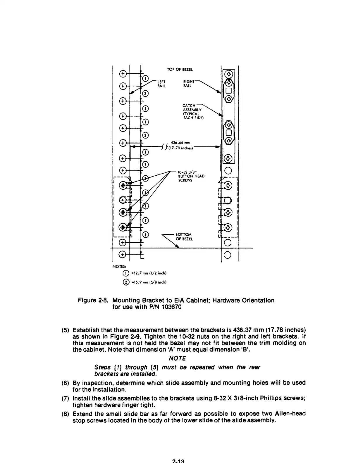
Figure
2·8.
Mounting Bracket to EIA Cabinet; Hardware Orientation
for use with
PIN
103670
(5)
Establish that the measurement between the brackets
is
436.37 mm (17.78 inches)
as shown in Figure 2-9. Tighten the
10-32 nuts on the right and left brackets.
If
this measurement is not held the bezel may not
fit
between the trim molding on
the cabinet.
Notethat
dimension 'A' must equal dimension 'B'.
NOTE
Steps [1] through
[5]
must be repeated
when
the
rear
brackets are installed.
(6)
By inspection, determine which slide assembly
and
mounting holes will
be
used
for
the Installation.
(7)
Install the slide assemblies to the brackets using
8-32
X 3/8-inch Phillips screws;
tighten hardware finger tight.
(8)
Extend the small slide bar
as
far forward
as
possible
to
expose two Allen-head
stop screws located in the body
of
the lower slide
of
the slide assembly.