~
:~::2l::
WASHER
IO-32X
3/8
.
PAr-;
HEAD
i
SCREVIi
!
~_-jf-
45 I .61
"'~
,
'1
i .78
:,.,d"ll!'u
-H-A
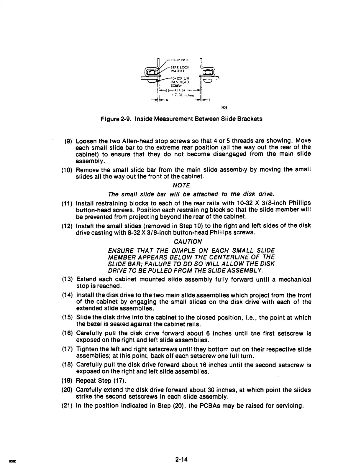
Figure 2-9. Inside Measurement Between Slide Brackets
(9)
Loosen the two Allen-head stop screws so that 4 or 5 threads are showing. Move
each small slide bar to the extreme rear position (all the way out the rear of the
cabinet) to ensure that they do not become disengaged from the main
slide
assembly.
(10)
Remove the small slide bar from the main slide assembly by moving the small
slides all the way out the front of the cabinet.
NOTE
The
small slide bar will be attached to the disk drive.
(11)
Install restraining blocks to
each
of the rear rails with 10-32 X 3/B-inch Phillips
button-head screws. Position
each
restraining block
so
that
thE:
slide member will
be
prevented from projecting beyond the rear of the cabinet.
(12)
Install the small slides (removed in Step 10) to the right and left sides
of
the disk
drive casting with
B-32
X 3/8-inch button-head Phillips screws.
CAUTION
ENSURE
THAT
THE
DIMPLE
ON
EACH
SMALL
SLIDE
MEMBER
APPEARS
BELOW
THE
CENTERLINE
OF
THE
SLIDE
BAR;
FAILURE
TO
DO
SO
WILL
ALLOW
THE
DISK
DRIVE
TO
BE
PULLED
FROM
THE
SLIDE
ASSEMBL
Y.
(13)
Extend
each
cabinet mounted slide assembly fully forward until a mechanical
stop is reached.
(14)
Install the disk drive to the two main slide assemblies which project from the front
of the cabinet
by
engaging the small slides on the disk drive with each
of
the
extended slide assemblies.
(15)
Slide the disk drive into the cabinet to the closed position, i.e., the point at which
the bezel is seated against the cabinet
ralls.
(16)
Carefully pull the disk drive forward about 6 inches until the first setscrew is
exposed on the right and left slide
assemblies.
(17)
Tighten the left and right setscrews until they bottom out
on
their respective slide
assemblies; at this point, back
off
each
setscrew one full turn.
(18)
Carefully pull the disk drive forward about
16
inches until the second setscrew is
exposed on the right and left
slide assemblies.
(19)
Repeat Step (17).
(20)
Carefully extend the disk drive forward about
30
inches, at which point
the-
51
ides
strike the second setscrews in
each
slide assembly.
(21)
In
the position indicated in Step (20), the PCBAs
may
be
raised for servicing.
2-14