The
amplified
read
signal is ac-coupled to a L-C filter stage which removes the undesirable
high-frequency noise signals superimposed
on
the
read
signal. The special quality of the
filter is its ability to pass the
read
signal with only small attenuation and negligible phase
variation.
4.6.3.4
Variable Gain Amplifier
The filtered
read
signal is amplified
by
the Variable Gain Amplifier stage. This amplifier
has a nominal voltage gain of approximately 7.3 under normal operating conditions; thus,
the
read
signal output is normally
350
to
650
mv
peak-to-peak. In the
read
margin test
mode, the gain
of
the amplifier stage is reduced to approximately 2.6.
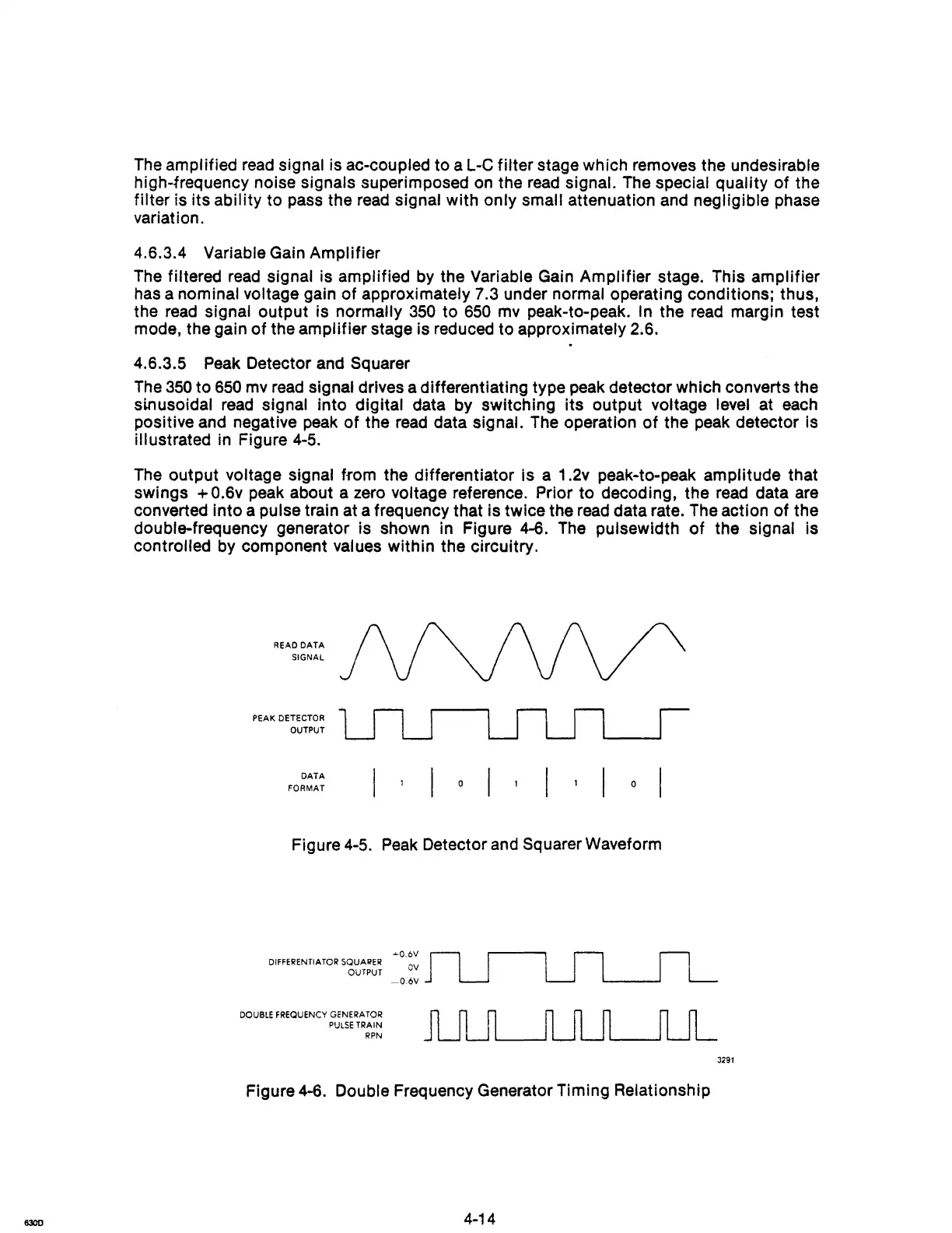
4.6.3.5
Peak
Detector and Squarer
The
350
to
650
mv
read
Signal drives a differentiating type peak detector which converts the
slnusoidal read signal into digital data by switching its output voltage level at each
positive and negative
peak
of
the
read
data signal.
The
operation
of
the peak detector is
illustrated
in
Figure
4-5.
The
output voltage signal from the differentiator is a 1.2v peak-to-peak amplitude that
swings
+ 0.6v peak about a zero voltage reference. Prior to decoding, the
read
data are
converted into a pulse train at a frequency that is twice the
read
data rate. The action
of
the
double-frequency generator is shown in Figure 4-6.
The
pulsewidth
of
the signal is
controlled by component values within the Circuitry.
READ
DATA
SIGNAL
PEAK DETECTOR
OUTPUT
DATA
FORMAT
o
o
Figure 4-5.
Peak
Detector and Squarer Waveform
DIFFERENTIATOR SQUARER
OUTPUT
DOUBLE FREQUENCY GoNERA
TOR
PULSE
TRAIN
RPN
....
O.6V
OV
-O.6V
Figure 4-6. Double Frequency Generator Timing Relationship
4-14
3291