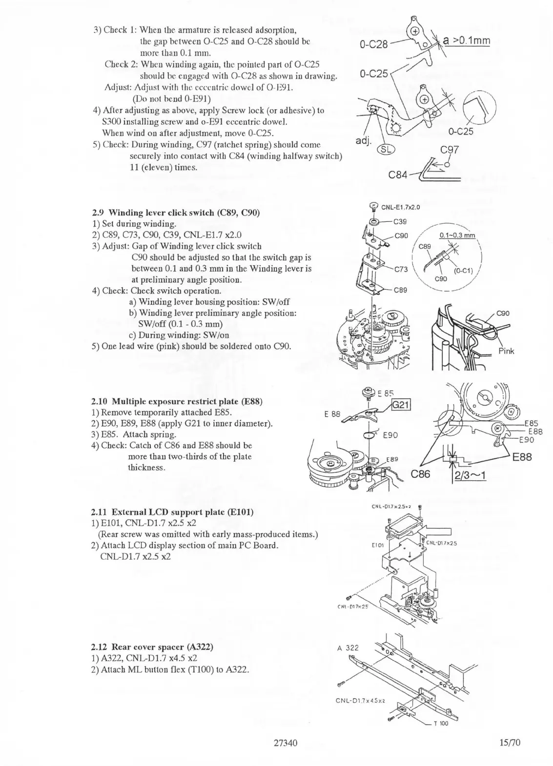
3) Check l : When the armature
is
released adsorption,
the gap
between O-C25
and
O-C28 should be
more
t.han
0.1 mm.
Check
2:
When winding again, the pointed part of O-C25
should he engaged with O-C28
as
shown
in
drawing.
Adjust: Adjust with the eccentric dowel
of
O-E91.
(Do not bend
O-E9
l)
4) After adjusting
as
above, apply Screw lock (or adhesive) to
S300 installing screw
and
o-E91 eccentric dowe
l.
When wind on after adjustment, move
O-C25.
5) Check: During winding, C97 (ratchet spring) should come
securely into contact with C84 (winding halfway switch)
11
(eleven) times.
2.9 Winding lever click switch (C89, C90)
1) Set during winding.
2) C89, C73,
C90, C39, CNL-El.7 x2.0
3) Adjust: Gap
of
Winding lever click switch
C90 should be adjusted so that the switch gap is
between
0.1 and
0.3
mm
in the Winding lever is
at preliminary angle position.
4)
Check: Check switch operation.
a)
Winding lever housing position: SW
/o
ff
b) Winding lever preliminary angle position:
SW/off (0.1 - 0.3 mm)
c) During winding: SW/on
5) One lead wire (pink) should be soldered onto C90.
~\c
O-C28
/~
>0.
1mm
~~~c
~
adj.
~
CNL-E1 .7x2.0
®--c39
__
_
,/
-,,
C90
/~
0
.
1-0
.3
mm
,
I C89 \
t
C73
\,
~
(O-C1))
\,"'- C90
/'
CB9
'-
---/
2.10 Multiple
exposure
restrict
plate (E88)
1) Remove temporarily attached E85.
2)
E90, E89, E88 (apply G21 to inner diameter).
~:ss
L~
EBB~~
-
3) E85. Attach spring.
4) Check: Catch
of
C86 and E88 should be
more than two-thirds
of
the plate
thickness.
2.11
External
LCD
support
plate
(ElOl)
1) ElOl, CNL-D1.7 x2.5 x2
(Rear screw was omitted with early mass-produced items.)
2) Attach LCD display section
of
main
PC
Board.
CNL-Dl.7 x2.5 x2
2.12
Rear
cover
spacer
(A322)
1) A322,
CNL-Dl.7
x4.5 x2
2) Attach
ML
button flex
(TlOO)
to
A322.
27340
CNL-Dl.7x2.5.,
~
f?
CNl·01
7
x2~
CNL-Dl.7x4
.
Sn
15170

 Loading...