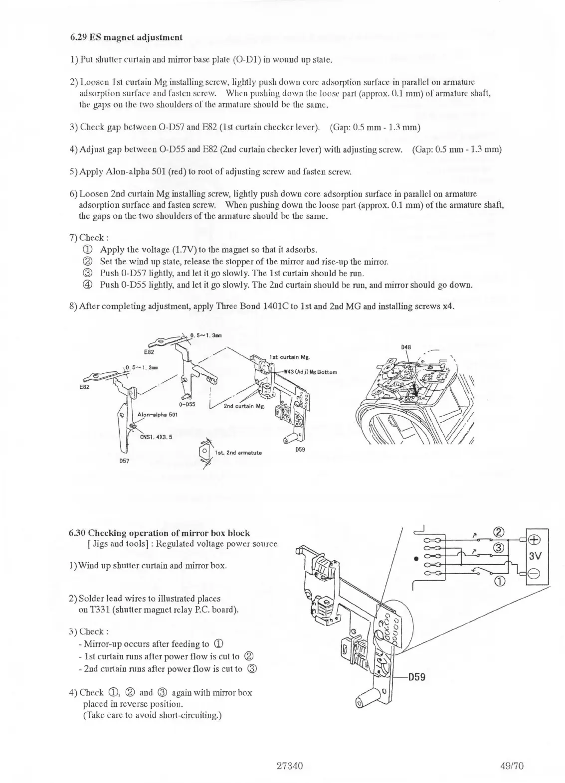
6.29
ES
magnet
adjustment
1)
Put shutter curtain and mirror base plate
(0
-
Dl)
in
wound up state.
2)
Loosen
1st curtain
Mg
installing screw, lightly push
down
core adsorption surfact·
in
parallel on armature.
adsorption surfac('. aud fasten screw.
Whrn
pushing down the loose par! (approx.
0.1
mm)
of
armature shaft,
the
gaps on the two shoulders of
th('.
armature should be the same.
3)
Check gap
between
O-D57 and E82 (1st curtain
checker
lever). (Gap: 0.5 mm - ]
.3
mm)
4)
Adjust
gap
between
O-D55 and E82 (2nd curtain
checker
lever) with adjusting screw. (Gap: 0.5 mm - 1.3 mm)
5)
Apply
Alon-alpha
501 (red) to root
of
adjusting screw and fasten screw.
6)
Loosen
2nd curtain
Mg
installing screw, lightly push
down
core adsorption surface
in
parallel on am1ature
adsorption
surface
and fasten screw. When pushing
down
the loose part (approx. 0.1
mm)
of
the
an11ature
shaft,
the
gaps
on
the
two
shoulders
of
the amiature should
be
the same.
?)Check:
CD
Apply
the
voltage
(l.7V)
to the magnet so that it adsorbs.
® Set
the
wind up state, release the stopper
of
the
mirror and rise-up the mirror.
@
Push
O-D57 lightly, and
Jet
it go slowly.
The
1st curtain should be run.
@)
Push
O-D55 lightly, and let
it
go slowly.
The
2nd curtain should be run, and mirror should go down.
8)
After
completing
adjustment, apply Three Bond 1401C to 1st and 2nd
MG
and
installing screws x4.
059
057
6.30
Checking
operation
of
mirror
box
block
f Jigs and tools] : Rei,rulated voltage
power
source.
1) Wind
up
shutter
curtain and mirror box.
2)
Solder
lead
wires
to illustrated places
on T331 (shutter magnet relay
P.C.
board).
3)Chcck:
- Mirror-up
occurs
after feeding to
CD
-
ls!
curtain runs after
power
flow is cut to ®
- 2nd curtain
nms
after
power
Oow is cut to @
4)
Check
CD,
® and @ again with mirror
box
placed in reverse position.
(Take
care
to avoid shm1-circuiting.)
27:340
048
49170

 Loading...