4. Body unit parts
• Disassembly aud assembly should be carried out iu accordance with thr following description and with reference
to
the parts list disassembly drawing.
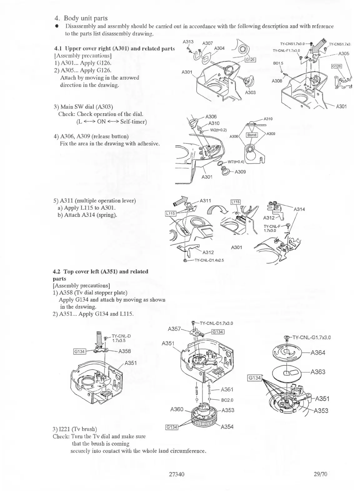
4.1 Upper
cover
right (A301) and related parts
IJ\sscmlily
prcl'<111tio11s]
I)
J\.301
...
Apply
C;
126.
2)
A305 ... Apply GJ 26. A301
Attach by moving
in
the arrowed
direction in the drawing.
3)
Maiu
SW
dial
(A.'J,03)
Check: Check operation
of
the dial.
(L
«---?
ON«---?
Self-timer)
4)
A306,
A309
(release button)
Fix
the.
area in the drawing with adhesive.
5)
A.'J,11
(multiple operation lever)
a) Apply
Ll
15 to A301.
b) Attach A314 (spring).
4.2
Top
cover left (A351) and related
parts
[Assembly precautions]
1) A358 (Tv dial stopper plate)
Apply G134 and attach by moving as shown
in the drawing.
2) A351... Apply G134 and L115.
3)
1221
(Tv brush)
Check: Turn the
Tv
dial and make sure.
that the brush is coming
securely into contact
wit!J
the.
whole land circumference.
27340

 Loading...