3. Body
II
• Disassembly and assembly should be carried out
in
accordance with the following description
and
with reference
to
th
e parts list disassembly drawing.
[Precautions
whrn
assembling)
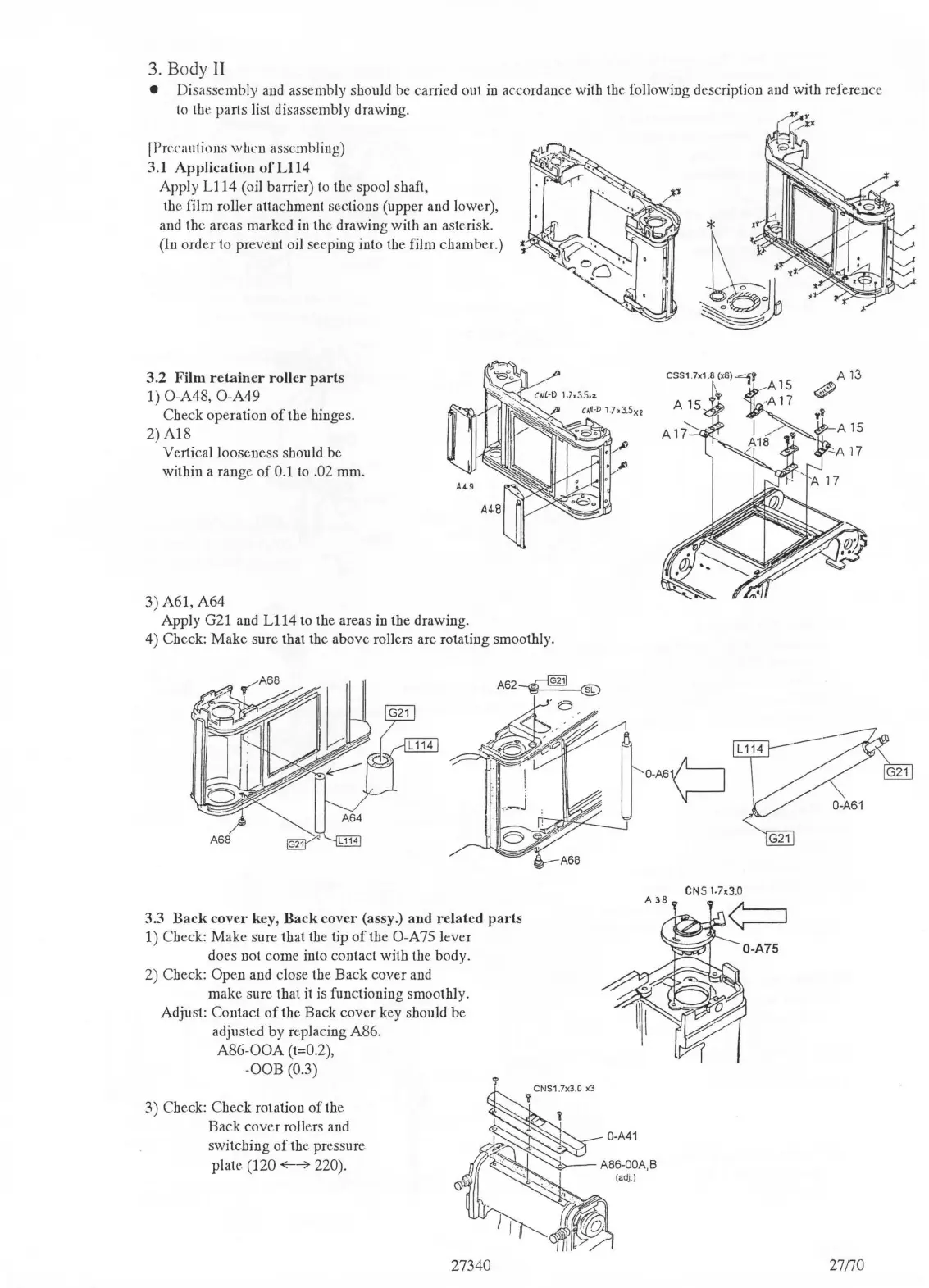
3.1
Application
ofL114
Apply
Ll
14 (oil barrier)
to
the spool shaft,
th
e film roller attachment sections (upper and lower),
and the areas marked
in
th
e drawing with
au
asterisk.
(ln order
to
prevent oil seeping into the film chamber.)
3.2
Film
retainer
roller
parts
1) O-A48, O-A49
Check operation
of
the hinges.
2)A18
Vertical looseness should be
within a range
of
0.1
to
.02 mm.
3) A61,
A64
Apply G21 and
Ll14
to the areas in the drawing.
4) Check: Make sure that the above rollers are rotating smoothly.
3.3
Back
cover
key,
Back
cover
(assy.)
and
related
parts
1) Check: Make sure that
th
e tip
of
the
0-A
75 lever
does not come into contact with the body.
2) Check:
Open and close
th
e Back cover and
make
sure.
that
it
is
fonctioning smoothly.
Adjust: Contact
of
the Back cover key should
be.
adjusted by replacing A86.
A86-00A
(t==0.2)
,
-OOB (0.3)
3)
Che.ck:
Check rotation
of
the
Back cover rollers and
switching
of
the pressure.
plate.
(120
~--o>
220).
27340
A13
<P
27{70

 Loading...