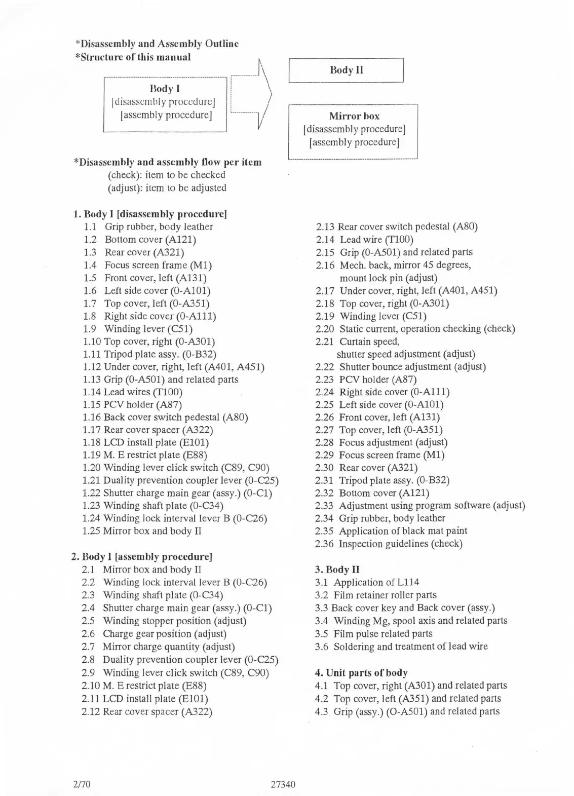
*Disassembly and Assembly Outline
*Structure
of
this
manual
f\
·
······
·•
················
i~
-
~~
-
;
-
·i·--
·
···· ···
·
·-
--
·········
:······
··
······
\
!disassembly proccdurcJ : )
[assembly procedure]
L
.....
........ ]/
*Disassembly
and
assembly flow
per
item
(check): item
to
be checked
(adjust): item
to
be adjusted
1. Body I [disassembly procedure]
1.1
Grip rubber, body leather
1.2 Bottom cover (A121)
1.3 Rear cover (A321)
1.4 Focus screen frame
(Ml)
1.5 Front cover, left (A131)
1.6 Left side cover (0-AlOl)
1.7 Top cover, left (O-A351)
1.8 Right side cover
(0-Alll)
1.9 Winding lever (C51)
1.10 Top cover, right (O-A301)
1.11 Tripod plate assy. (O-B32)
1.12 Under cover, right, left (A401, A451)
1.13 Grip
(O-A501) and related parts
1.14 Lead wires
(TlOO)
1.15 PCV holder (A87)
1.16 Back cover switch pedestal
(A80)
1.17 Rear cover spacer (A322)
1.18 LCD install plate
(ElOl)
1.19
M.
E restrict plate (E88)
1.20 Winding lever click switch (C89, C90)
1.21 Duality prevention coupler lever (O-C25)
1.22 Shutter charge main gear (assy.)
(0-Cl)
1.23 Winding shaft plate (O-C34)
1.24 Winding
Jock
interval lever B (O-C26)
1.25 Mirror box and body
II
2. Body I [assembly
procedure]
2.1 Mirror box and body
II
2.2 Winding lock interval lever B (O-C26)
2.3 Winding shaft plate (O-C34)
2.4 Shutter charge main gear (assy.)
(0-Cl)
2.5 Winding stopper position (adjust)
2.6 Charge gear position (adjust)
2.7 Mirror charge quantity (adjust)
2.8 Duality prevention coupler lever
(O-C25)
2.9 Winding lever click switch (C89, C90)
2.10
M.
E restrict plate (E88)
2.11 LCD install plate
(ElOl)
2.12 Rear cover spacer (A322)
Body II
Mirror
box
~]
[disassembly procedure]
[ assem b
I y procedure]
----------------
----
--------------------------------------------·-
--
--
2.13 Rear cover switch pedestal (A80)
2.14 Lead wire
(TlOO)
2.15 Grip (O-A501) and related parts
2.16 Mech. back, mirror 45 degrees,
mount lock pin (adjust)
2.17
Under cover, right, left (A401, A451)
2.18 Top cover, right
(O-A301)
2.19 Winding lever (C51)
2.20 Static current, operation checking (check)
2.21 Curtain speed,
shutter speed adjustment (adjust)
2.22
Shutter bounce adjustment (adjust)
2.23
PCV holder (A87)
2.24 Right side cover
(0-Alll)
2.25 Left side cover (0-AlOl)
2.26 Front cover, left
(Al31)
2.27 Top cover, left (O-A351)
2.28 Focus adjustment (adjust)
2.29 Focus screen frame
(Ml)
2.30 Rear cover (A321)
2.31 Tripod plate assy.
(O-B32)
2.32 Bottom cover (A121)
2.33 Adjustment using program software (adjust)
2.34 Grip rubber, body leather
2.35 Application of black mat paint
2.36 Inspection guidelines (check)
3. Body II
3.1 Application of L114
3.2 Film retainer
roller parts
3.3 Back cover key and Back cover (assy.)
3.4 Winding Mg, spool axis and related parts
3.5 Film pulse related parts
3.6 Soldering and treatment
of
lead wire
4.
Unit
parts
of
body
4.1 Top cover, right
(A301) and related parts
4.2 Top cover, left (A351) and related parts
4.3 Grip (assy.)
(O-A501) and related parts
2170
27340

 Loading...