2.13
Rear
cover
switch pedestal (A80)
1) Open the Back cover.
2)A85
3) A80, switch contac
t.
4) Move A80 forward
to
the left
and
attach.
CNL-D1.7 x2.5, CNM 1.7
x5
.5
5) Check: Back cover switch, pressure plate switch.
Each switch should go
on
and
off securely
hy
opening and closing the Back cover and
switching the pressure plate
(120-E--?220).
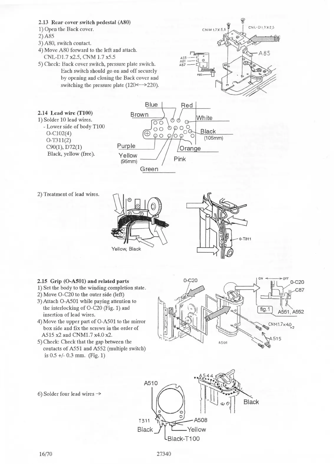
2.14
Lead
wire
(TIOO)
1)
Solder 10 lead wires.
- Lower side
of
body
TIOO
O-C102(4)
O-T311(2)
C90(1
),
D72(1)
Black, yellow (free).
Green
2) Treatment
of
lead wires.
2.15
Grip
(0-ASOl)
and
related
parts
1) Set the body to the winding completion state.
2) Move
O-C20 to the outer side (left)
3) Attach
O-A501 while paying attention
to
the interlocking
of
O-C20 (Fig. 1)
and
insertion
of
lead wires.
4) Move the. upper part
of
O-A501 to the mirror
box side and fix the screws in the order
of
A515
x2
and
CNMl.7
x4.0 x2.
5) Check: Check that the gap
betwee.n the
contacts
of
A551 and A552 (multiple switch)
is
0.5 +/- 0.3 mm. (Fig. 1)
A510
6) Solder four lead wires
-7
0
16/70
27340
CNL
-
[)
1. 7 X
2
.
~'
Black
(105mm)
e

 Loading...