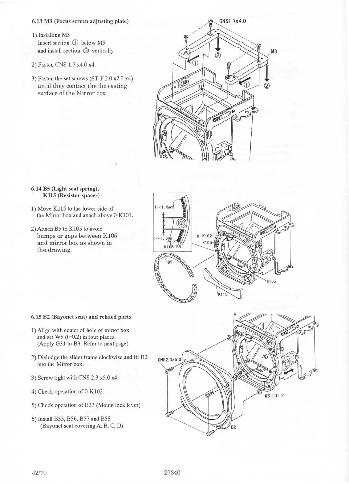
6.13 M3 (Focus screen adjusting plate)
1) Installing
M3
Insert section
CD
below
MS
and install section ® vertically.
2)
Fasten CNS 1.7 x4.0 x4.
3) Fasten the set screws (ST-F
2.0 x2.0 x4)
until
they contact.
t.he
die casting
surface of
the
Mirror
box.
6.14 BS (Light seal spring),
·
KUS
(Resistor spacer)
1) Move K115 to the lower side
of
the Mirror box and attach above 0-KlOl.
2) Attach
BS
to K105 to avoid
bumps
or gaps between
K105
and
mirror
box as shown in
the
drawing.
6.lS
B2 (Bayonet seat)
and
related
parts
1) Align with center
of
hole
of
mirror box
and set W8 (t=0.2) in four places.
(Apply G31
to
B3. Refer to next page)
2) Dislodge the slider frame clockwise
and
fit B2
into the Mirror box.
3) Screw tight with CNS 2.3
x5
.0 x4.
4)
Check operation
of
O-K.102.
5) Check operation
of
B33 (Mount lock lever)
6) Install B55, B56, B57
and
B58
(Bayonet seat covering A, B,
C,
D)
42170
M3
27:340

 Loading...