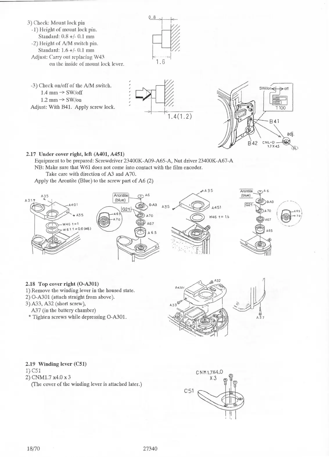
3) Check: Mount lock pin
-1) Height
of
mount lock pin.
Standard: 0.8 +
/-
0.1
mm
-2)
Height
of
NM
switch pin.
Standard: 1.6 +
/-
0.1
mm
Adjust:
Carry out replacing W43
OJI the inside
of
mount Jock lever.
-3) Check
on/
off
of
the
NM
switch.
1.4 mm
-7
SW
/
off
1.2
mm
-7
SW
/on
Adjust: With B41. Apply screw lock.
·
~
L 1.4(1.2)
2.17
Under
cover right, left (A401, A451)
Equipment to be prepared:
Scr
ewdriver 23400K-A09-A65-A, Nut driver 23400K-A67-A
NB:
Make
sure that W61 does not come into contact with the film encoder.
Take care with direction
of
A3 and
A70.
Apply
the Arontite (Blue) to the screw part
of
A6
(2)
ArontiteL e A6
(
blu
fie)
I
---t;
O-A
3
1
A
6
A70
~
"'
•
@A65
~
2.18
Top
cover
right
(0-A301)
1)
Remov
e the
winding
lever in the housed state.
2)
0-A301
(attach straight from above).
3) A33,
A32
(short screw),
A37
(in the battery chamber)
* Tighten screws while depressing O-A301.
2.19
Winding
lever (CSl)
1)
C51
2) CNMl.7 x4.0 x 3
(fhe
cover
of
the winding lever is attached later.)
18170
27340
_.,A
35
'"~""
©
W46t=
1
.b
C51
•
8~41
.
B42
CNL-D
l.
7X
.5
SL
)
,_
~
Arontite
~A
6
(
blue)
·
-~
[G2Tl:
::3
(/
@j=
.
•ES\
. A
10:
A67
\.
../·
.. ·
~

 Loading...