2.
Body I (assembly procedure)
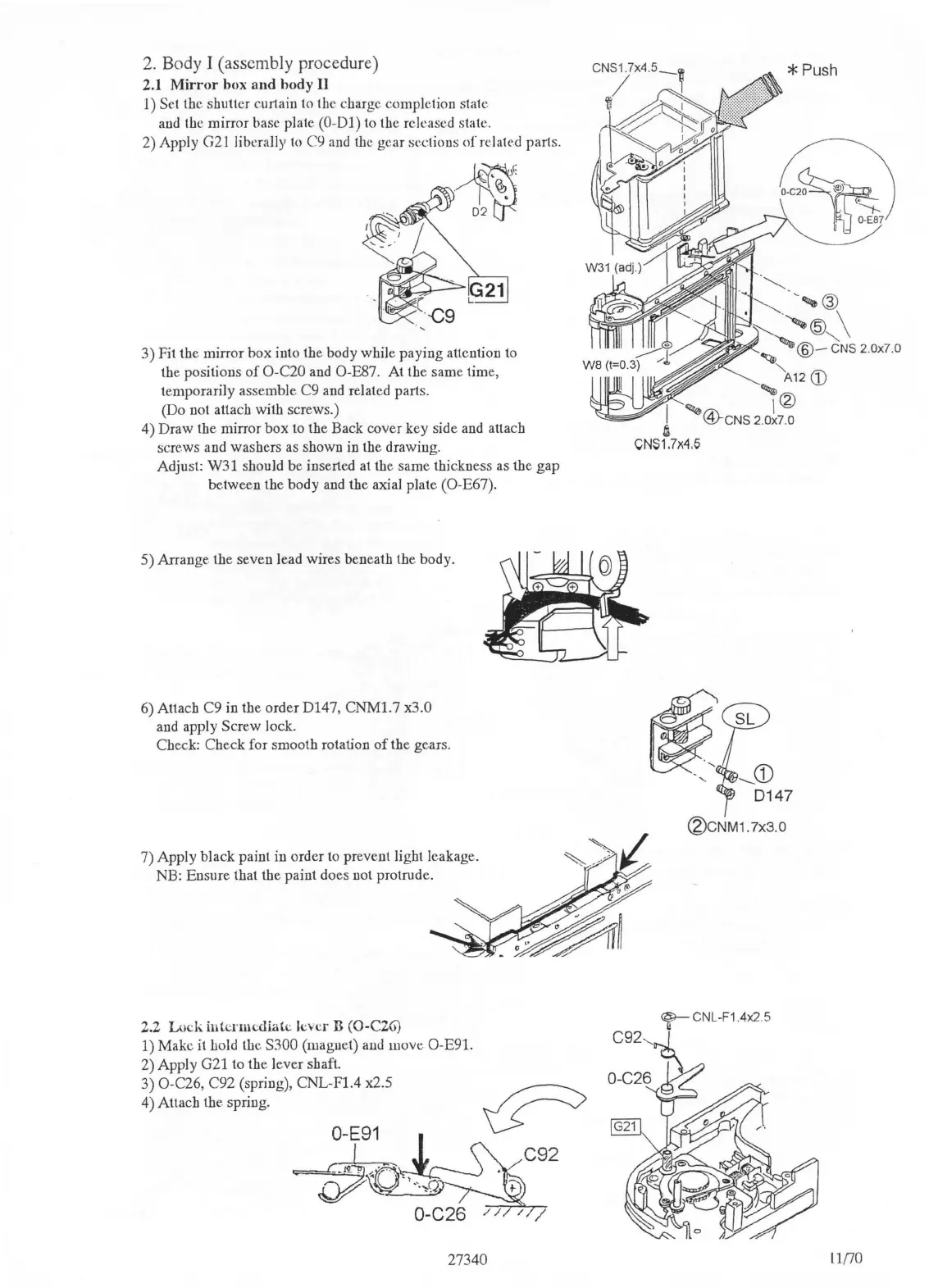
2.1
Mirror
box
and
hody
II
l)
Set the shutter curtain to the charge completion state
and
the mirror base plate (0-01) to the released state.
2) Apply
G21
liberally
to
C9
and
the gear sections
of
related parts.
3) Fit the mirror box into the body while paying attention
to
the positions
of
O-C20
and
O-E87. At the same time,
temporarily assemble C9
and
related parts.
(Do not attach with screws.)
4) Draw the mirror box to the Back cover key side
and
attach
screws and washers
as
shown in the drawing.
Adjust: W31 should be inserted at the same thickness
as
the gap
between the body
and
the axial plate (O-E67).
5) Arrange the seven lead wires beneath the body.
6) Attach C9 in the order D147,
CNMl.7
x3.0
and
apply Screw lock.
Check: Check for smooth rotation
of
the gear
s.
7) Apply black paint in order to prevent light leakage.
NB: Ensure that the paint does not protrude.
2.2
Lock
intermediate
lever B
(0
-
C2G)
1) Make
it
hold the S300 (magnet)
and
move O-E91.
2) Apply G21 to the lever shaft.
3) O-C26, C92 (spring), CNL-Fl.4 x2.5
_
~
4) Attach the spring. \..>
27340
.
~-
~
"--......_
'
'®
·
~'@
\
~
@-'cNs
2.
0x7
.0
'A12
CD
'
'
1®
®-cNS
2.ox?.o
I
~
CN$1.7x4.5
-CD
0147
®cNM1.7x3.0
<f'-
CNL-F14x2 5
C92
....._
i
O-C26
nno

 Loading...