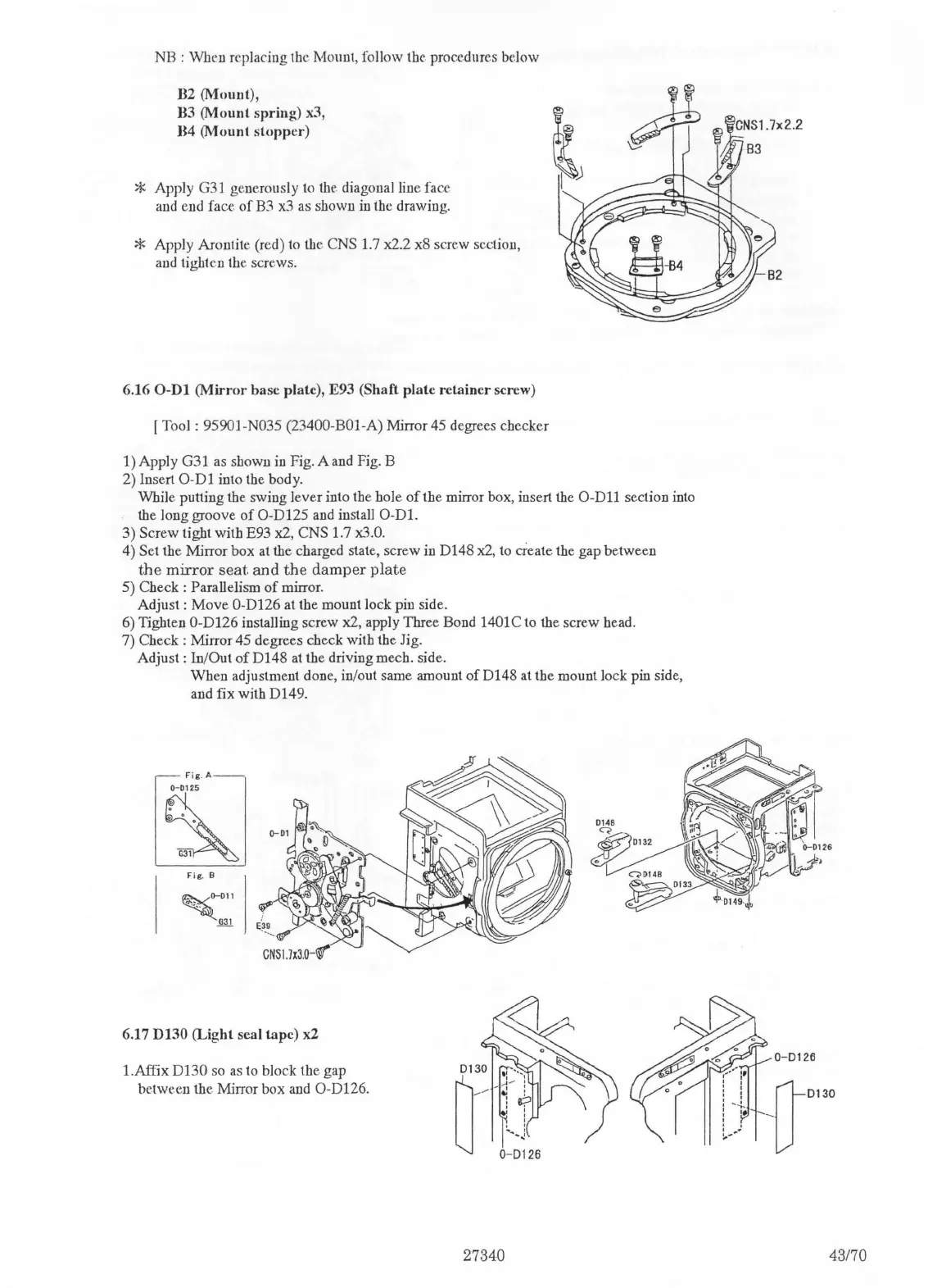
NB : When replacing the Mount, follow the procedures
be.low
B2 (Mount),
B3
(Mount
spring) x3,
H4
(Mount
stopper)
* Apply G31 generously
to
the diagonal line face
and end face
of
B3
x3
as shown
in
the drawing.
* Apply Arontite (red)
to
the CNS 1.7 x2.2 x8 screw section,
and tighten the screws.
6.16
0-Dl
(Mirror
base plate), E93 (Shaft plate retainer screw)
[Tool:
95901-N035 (23400-BOl-A) Mirror 45 degrees checker
1) Apply G31 as shown
in
Fig. A
and
Fig. B
2) Insert
0-Dl
into the body.
~)
While putting the swing lever into the hole
of
the mirror box, insert the
0-Dll
section into
the long groove
of
O-D125 and install
0-Dl.
3) Screw tight with E93 x2, CNS 1.7
x3
.
0.
4) Set the Mirror box
at
the charged state, screw in D148
x2,
to create the gap between
the
mirror
seat
and
the
damper
plate
5) Check : Parallelism
of
mirror.
Adjust:
Move
O-D126 at the mount lock pin side.
6) Tighten
O-D126 installing screw x2, apply Three Bond 1401C to the screw bead.
7)
Check : Mirror 45 degrees check with the Jig.
Adjust:
In/Out
of
D148
at
the driving mecb. side.
When adjustment done, in/out same amount
of
D148 at the mount lock pin side,
and fix with D149.
Fig
.
A--
~
Fig.
B
6.17 D130 (Light seal tape) x2
I.Affix D130 so
as
to block the gap
between the Mirror box and
O-D126.
0130
~···.
~
''
~ -
:
--
.:
:
:
e:::i
I !
' '
.....
'
0-~~
26
27340
0-0126
43170

 Loading...