7.
0-01
(mirror base plate) assembly
7.1
0-Dll
(Mirror
actuator
arm),
0-014
(Center
gear
assy.), D17
(Mirror
operation plate), etc.
[Adhesive! : 9590 I S 120 (Arontitc
red
50cc)
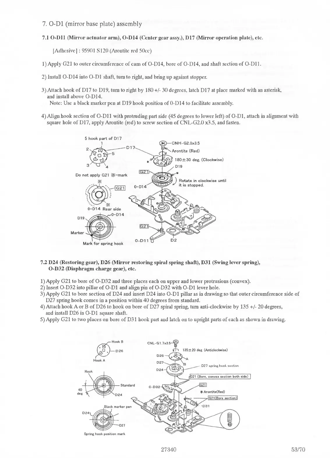
1) Apply
G21
lo outer circumfrrence
of
cam
of
O-D14, bore
of
O-D14,
and
shaft section
of
0-DJ
1.
2) lustall O-D14 into
0-Dl
shaft, tum to right,
aud
briug up agaiust stopper.
3)
Attach book
of
Dl
7 to
Dl
9,
tum to right by 180
+/
- 30 degrees, latch D17
at
place marked with
au
asterisk,
and
install above
O-Dl4.
Note: Use a black marker pen
at
Dl
9 hook position
of
0-
014
to facilitate assembly.
4) Align book sectiou
of
0-Dl
1 with protruding part side (45 degrees to lower left)
of
0-01,
attach
in
alignment with
square bole
of
Dl
7, apply Arontite (red)
to
screw section
of
CNL-G2.0 x3.5,
and
fasten.
Do
not
apply
G21
*-mark
:~---
~
··--[fil]
' .
' :
-.
'
\ 0 •
\,..
\t«
0-014
Rear
side
•
014
019
Marker
02
Mark
for
spring
hook
7,2 D24 (Restoring gear), D26
(Mirror
restoring
spiral
spring
shaft), D31 (Swing lever spring),
O-D32
(Diaphragm
charge
gear), etc.
1) Apply G21 to bore
of
O-D32
and
three places each on upper and lower protrnsions (convex).
2)
Insert O-D32 into pillar
of
0-Dl
and align pin
of
O-D32 with
0-Dl
lever hole.
3) Apply G21 to bore section
of
D24 and insert D24 into
0-Dl
pillar
as
in
drawiug
so
that outer circumference side
of
D27 spring hook comes in a position within 40 degrees from standard.
4) Attach hook A or B
of
D26 to hook on bore
of
D27 spiral spring, tum anti-clockwise by 135 +/- 20 degrees,
and
install D26
in
0-Dl
square shaft.
5)
Apply G21 to two places on bore
of
D31 hook part
and
latc!J
on to upright parts
of
each
as
shown
in
drawing.
024
~HookB
~-026
Hook A
Black
marker
pen
027
Spring hook position mark
CNL-Gl
.
7x3
.
S-~
rn
135±20
deg. (Anticlockwise)
026--(~'-A
027~~
\B
-----
027
spring
boo.._
5ec
t1on
024
~:::i
-,
----
' . .
G21
(Bo
re
,
convex
section
both
side)
53170

 Loading...