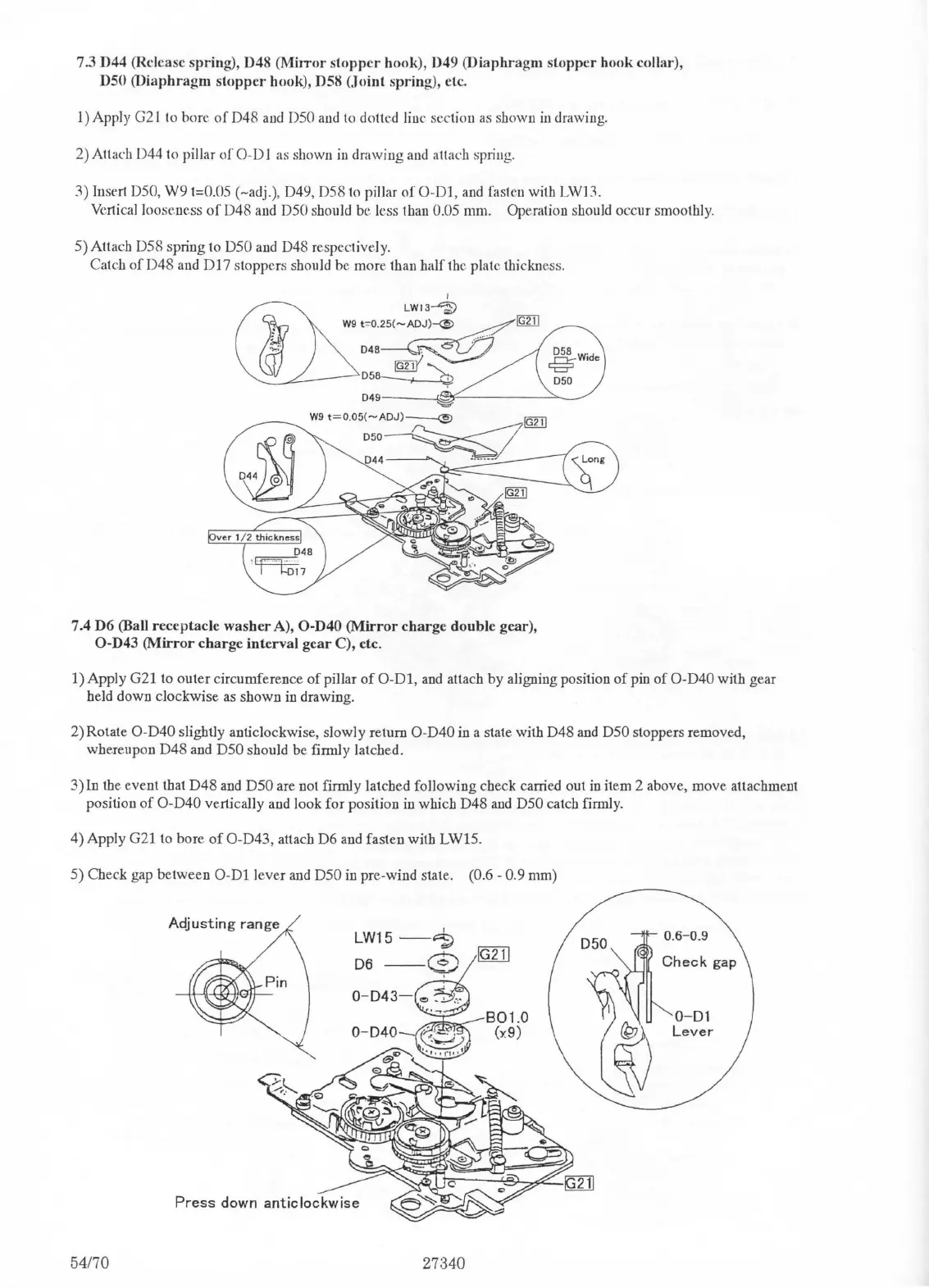
7.3 D44 (Release spring), D48 (MiJTor
stopper
hook),
049
(Diaphragm
stopper
hook collar),
DSO
(Diaphragm
stopper
hook), D58
(Joint
spring), etc.
1)
Apply
G2
J
to
bore
of
D48
and
D50
and
to
dotted line section as shown
in
drawing.
2)
Attach D44
to
pillar
of
0-D
J as shown
in
drawing
and
attach spriug.
3) Insert D50,
W9
t=0.05 (-adj.), D49, D58
to
pillar
of
0 -
Dl,
and
fasten with
LWH
Vertical looseness
of
D48
and
D50 should be less than 0.05 mm. Operation should occur smoothly.
5) Attach D58 spring to
D50
and
D48 respectively.
Catch
of
D48 and
DI
7 stoppers should be more than half
th
e plate thiclmess.
I
LW13~
W9
t
=
0
.
25(-A~[gliJ
048~
-
~"'
058~
049~~~~"§-'2(-~~~~
~-'>...~/
W9
t=0
.
05(-AOJ)--©
[gliJ
:::~
7.4 D6 (Ball receptacle
washer
A), O-D40
(Mirror
charge
double
gear),
O-D43
(Mirror
charge
interval
gear
C), etc.
1) Apply G21 to outer circumference
of
pillar
of
0-Dl,
and
attach by aligning position
of
pin
of
O-D40 with gear
held down cJockwise as shown in drawing.
2)Rotate
O-D40 slightly anticJockwise, slowly return O-D40
in
a state with D48
and
D50 stoppers removed,
whereupon D48 and
D50 should be firmly latched.
3)ln
the.
event that
D48
and
D50 are not firmly latched following check carried out
in
item 2 above,
move.
attachment
position
of
O-D40 vertically and look for position
in
which D48
and
D50 catch firmly.
4) Apply G21 to bore
of
O-D43, attach D6
and
fasten with LW15.
5) Check gap between
0-Dl
lever
and
D50
in
pre-wind state. (0
.6
- 0.9 mm)
54170
LW15
-1;
D6--$
0-Dl
Lever

 Loading...