Device Standards
HD11 XE Getting Started
4535 612 62651
6
136
Table 6-8 lists the recommended separation distances for the ultrasound system.
The conducted RF test level is 3 V and the system has a compliance level of
0.01 V. For the system, this means that the imaging system is extremely sensitive
to RF interference in the transducer passband. For example, for a 5-MHz imaging
transducer, the frequency range of interference from a 3-V/m field may be from 2
to 10 MHz, and manifests as itself as described in Table 6-7.
The 0.01-V level is where the interference becomes acceptable to some clinical
specialists.
NOTE
Sensitivity to interference is dependent on operating mode and imaging control
settings. The system has been tested while set to its maximum gain setting, mak-
ing it very susceptible to interference. You might not use your system at this set-
ting, but it represents a worse-case condition.
The order of increasing sensitivity, using these settings, as a function of operating
mode is 2D mode, 3D/4D mode, M-mode, Color mode, PW Doppler mode, and
CW Doppler mode. The system is more sensitive to interference in the CW
Doppler or PW Doppler operating modes but the probability of interference is
lower than 2D mode or Color mode because the susceptible frequency range is
less. Therefore, you are more likely to see interference in 2D or Color modes.
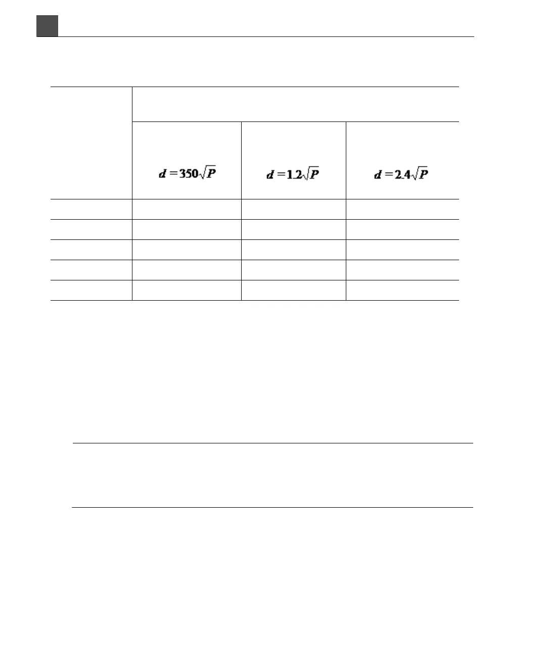
Table 6-8 Recommended Separation Distances
Rated
Maximum
Output
Power of
Transmitter
(Watts)
Separation Distances According to Frequency of
Tr a n s m i t t e r ( M e t e r s )
150 kHz to
80 MHz
80 to 800 MHz
800 MHz to
2.5 GHz
0, 01 35 m 0.12 m 0.24 m
0, 1 110 km 0.38 m 0.76 m
1 350 m 1.2 m 2.4 m
10 1.1 km 3.8 m 7.6 m
100 3.5 km 12 m 24 m