10
HD11 XE Getting Started
4535 612 62651
237
TEE Transducers
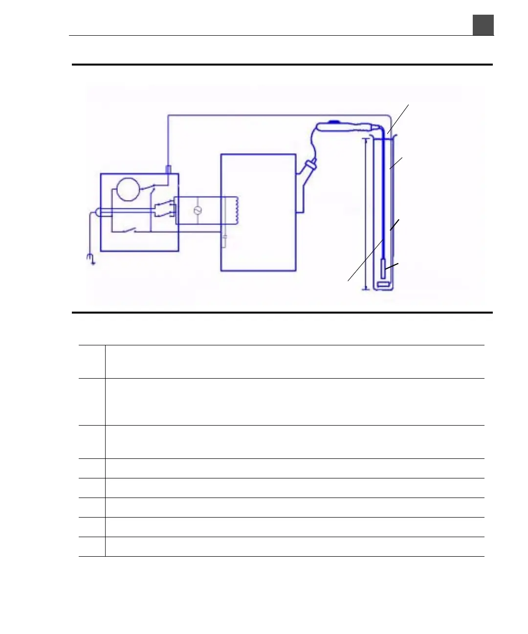
Figure 10-12 Electrical Safety Check Procedure for TEE Transducers
Key:
C Stray capacitance from the ultrasound system power wiring to the system
grounded metal chassis (1 to 3 MΩ reactance)
Z Impedance between the metal parts of the TEE transducer and a test
electrode placed in the bucket of saline solution (about 850 kΩ with an intact
outer insulating layer, 500 Ω with a hole in the layer)
A Microammeter to measure third-wire current, either directly from the chassis
or through Z to the test electrode
e Line power source, either 110 Vac or 220 Vac
i Current caused by e and stray capacitance, and optionally Z
S1 Open Earth Lift Ground switch
S2 Line Polarity switch
S3 Microammeter switch
i
Insulating outer layer
internal metal sheath
Saline
Test tube
(nonconductive)
Test electrode
TEE transducer
3.3 ft
(1 m)
Ultrasound system
(metal chassis)
Safety analyzer
S3
A
S2
i
L
e
N
E
C
i
S1