Device Standards
HD11 XE Getting Started
4535 612 62651
6
140
ARNINGS
• Do not use the foot switch in the operating room.
• Do not apply voltages of more than ±15 V with respect to ground to external
panel input connectors.
• The network interface connection connector is not intended for direct con-
nection to the telephone lines.
• If you have a modem, make sure it is not connected to a telephone line while
you are performing an ultrasound exam on a patient.
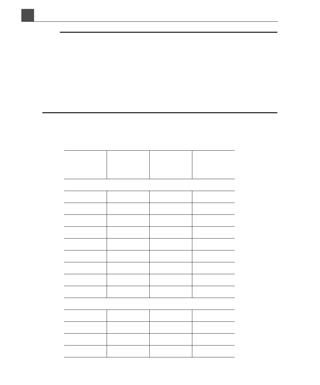
Table 6-10 lists the signal descriptions and nominal voltages for connectors on the
I/O panel.
Table 6-10 I/O Panel Pinouts
Pin Signal
Input/
Output
Maximum
Output
Volt age
RS-232 Serial Data Export
1DCDI --
2RXDI --
3TXDO±12V
4 DTR O ±12 V
5Ground----
6DSRI --
7 RTS O ±12 V
8CTSI --
9RII --
Foot Switch Input
1RightI 6V
2Middle I 6V
3N/C----
4 Left I 6 V