Intraoperative Transducers
HD11 XE Getting Started
4535 612 62651
12
256
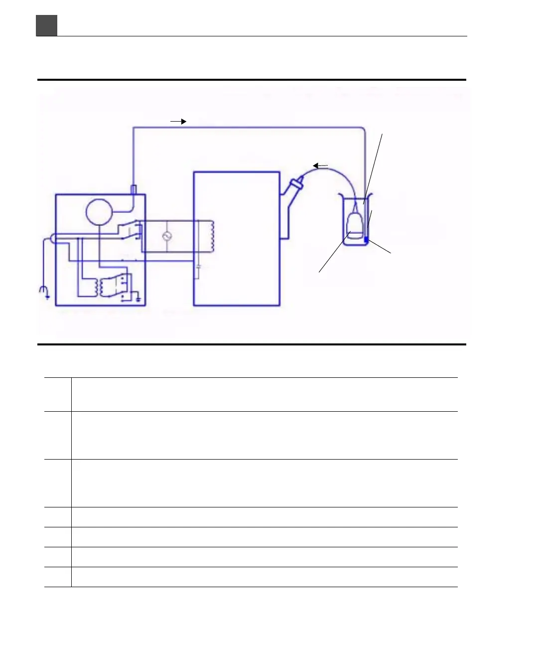
Figure 12-4 Test 2—Transducer Leakage Current Te s t w i t h M a i n s Vo l t a g e
Applied (Sink)
Key:
C Stray capacitance from the ultrasound system power wiring to the system
grounded metal chassis (1 to 3 MΩ reactance)
Z Impedance between the metal parts of the transducer and a test electrode
placed in the bucket of saline solution (about 850 kΩ with an intact outer
insulating layer, 500 Ω with a hole in the layer)
A Microammeter to measure leakage current from a line supply to the
transducer and back to Earth Ground through electrode Z and the equipment
chassis
e Line power source, either 110 Vac or 220 Vac
i Current caused by e and stray capacitance, and optionally Z
S1 Open Earth Lift Ground switch
S2 Line polarity switch
i=less than 50 µA
Ultrasound system
(metal chassis)
i
Z
Saline
Test container
(nonconductive)
Intraoperative transducer
immersed in saline
Test electrode
Safety analyzer
A
S2
N
e
S1
C
S3
E
L