User’s Manual of IGS-10020HPT-U
150
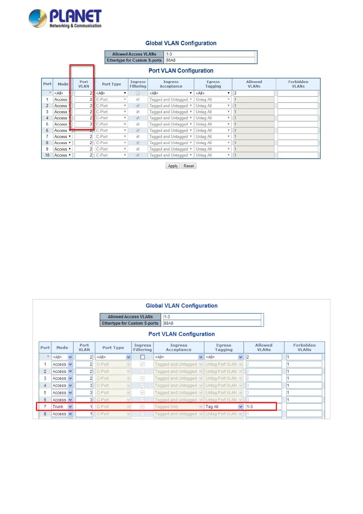
Figure 4-3-3-13: Changes Port VLAN of Port 1~3 to be VLAN2 and Port VLAN of Port 4~6 to be VLAN3
For the VLAN ports connecting to the hosts, please refer to 4.6.10.1 examples. The following steps will focus on the VLAN
Trunk port configuration.
1. Specify Port-7 to be the 802.1Q VLAN Trunk port.
2. Assign Port-7 to both VLAN 2 and VLAN 3 at the VLAN Member configuration page.
3. Define a VLAN 1 as a “Public Area” that overlapping with both VLAN 2 members and VLAN 3
members.
4. Assign the VLAN Trunk Port to be the member of each VLAN – which wants to be aggregated. For
this example, add Port-7 to be VLAN 2 and VLAN 3 member port.
5. Specify Port-7 to be the 802.1Q VLAN Trunk port, and the Trunking port must be a Tagged port
while egress. The Port-7 configuration is shown in Figure 4-3-3-14.
Figure 4-3-3-14: VLAN Overlap Port Setting & VLAN 1 – The Public Area Member Assign
That is, although the VLAN 2 members: Port-1 to Port-3 and VLAN 3 members: Port-4 to Port-6 also belongs to VLAN 1. But
with different PVID settings, packets form VLAN 2 or VLAN 3 is not able to access to the other VLAN.
6. Repeat Steps 1 to 6, set up the VLAN Trunk port at the partner switch and add more VLANs to join
the VLAN trunk, repeat Steps 1 to 3 to assign the Trunk port to the VLANs.

 Loading...