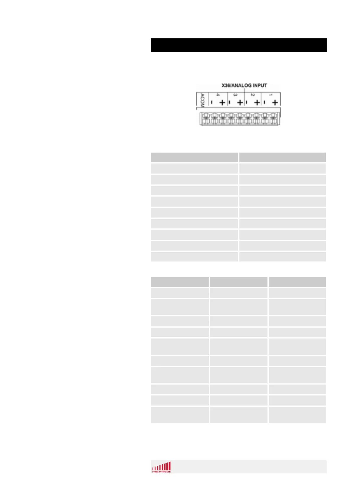
The analog inputs are connected with a 9 pole terminal block
(Fig. 92).
Fig. 92: Analog inputs terminal block
Pin Description
Pin 1 + input channel 1
Pin 2 - input channel 1
Pin 3 + input channel 2
Pin 4 - input channel 2
Pin 5 + input channel 3
Pin 6 - input channel 3
Pin 7 + input channel 4
Pin 8 - input channel 4
Pin 9 analog ground (ACOM)
Property Value Unit
Input signal range -10 - +10 V
Common mode
range
-15 - +15 V
Max. input voltage -15 - +15 V
Input impedance 16 kΩ
Max. bipolar zero
error
+/- 10 mV
Max. full scale error +/- 1 %
Max. channel to
channel mismatch
+/- 1 %
Max. linearity error +/- 4.88 mV
Resolution 4.88 mV
Conversion time /
4points
160 μs
Connection
Pin Assignment
Input Characteristics
PA 8000 PAMIO
PAMIO Components
12.01.2017 | 111
 Loading...