access" on page49 procedure.
Note:You can also access the jackscrew by laying the treadmill on its side, see "Side
lift platform assembly access" on page49 procedure.
3. Access the service menu (51765761) and select INCLINE TEST. Use the incline con-
trol to set the incline level to 14.
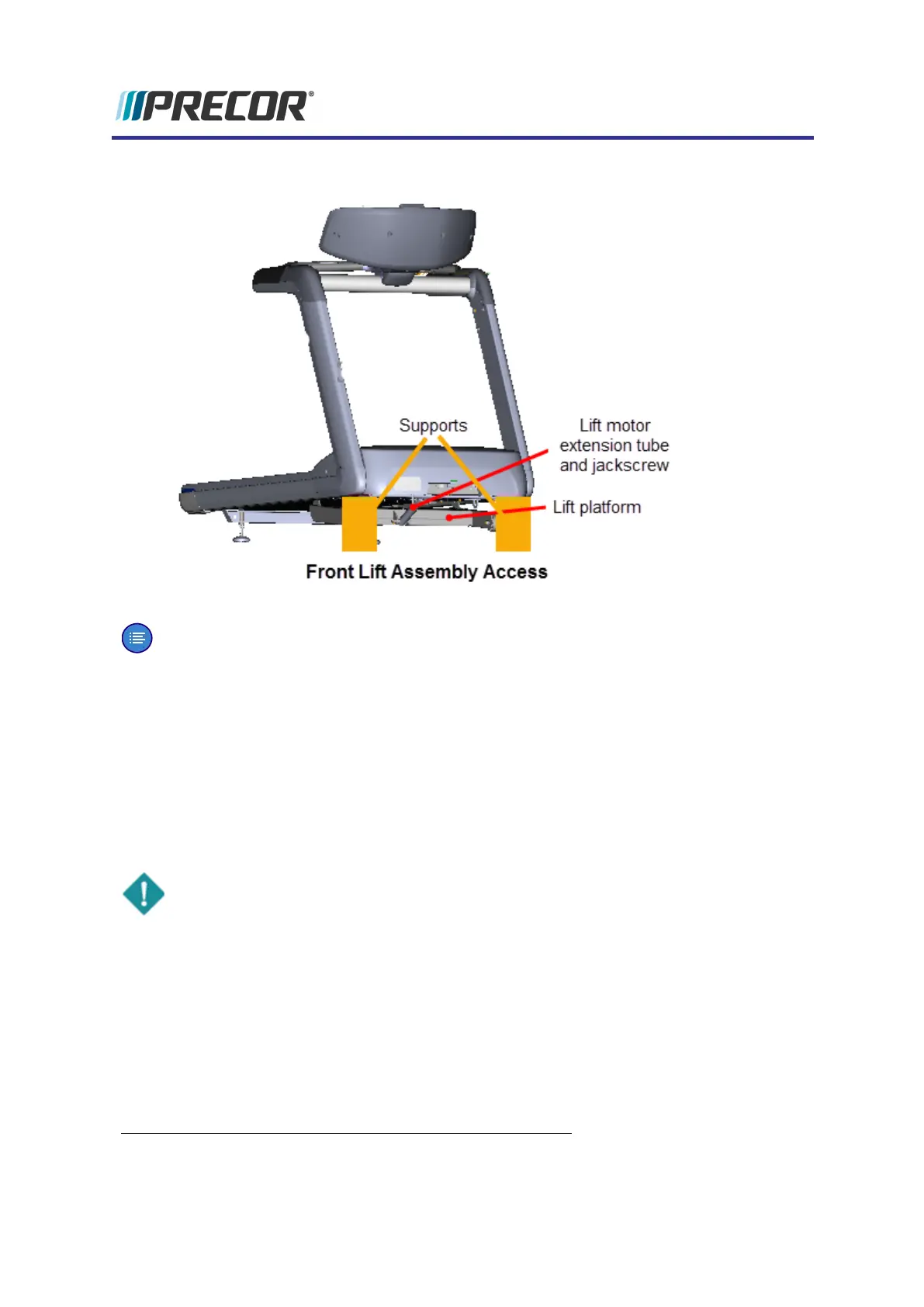
4. Securely and safely place supports (e.g. car jack stands) under the left and right front
corners of the frame weldment.
5. Slowly lower the incline level in 0.5 increments until the complete weight of the frame is
setting on the supports. Verify the supports are stable and secure carrying the weight of
the treadmill. Continue lowering the incline level to "0". Incline level "0" is the lift motor
calibration reference incline level.
IMPORTANT: Its important to set the incline level to "0" (calibration ref level) before
switching the power OFF.
6. Switch the power OFF and unplug
1
the power cord.
7. Disconnect the lift motor interface cable from the MC
2
"LIFT" connector. Remove the
interface cable from the cable routing clamp.
1
Disconnect a device power cord plug or cable connector from the power receptacle or outlet.
2
Motor Controller Module
Experience Series 700 Line Treadmills
123
5 Replacement Procedures
Lift Motor Replacement