Measuring and control behaviour
of the controller during calibration
During calibration the actuating outputs
are deactivated. Exception: a basic
load or a manual control variable has
been set. This remains active. The
measured value output
[standard signal output mA] is frozen,
corresponding to its settings in the mA
output menu.
When calibration/testing has been com‐
pleted successfully, all of the error
checks relating to the measured value
are restarted. The controller saves all
the determined data for zero point and
slope upon a successful calibration.
Buffer used
Dispose of the used buffer solution. For
more information: refer to the buffer sol‐
ution safety data sheet.
You need one test container with a buffer solu‐
tion for calibration.
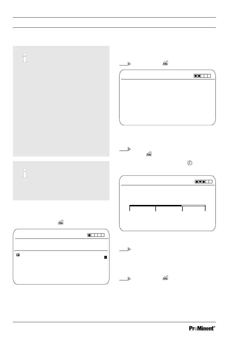
Continuous display ➨
CAL ORP
Pot. equalisation
Calibration process
A1027
No
0.0 mV
Offset
Last calibration
CAL setup
13:26:11
11/04/2013
continue with <CAL>
1 point
Fig. 48: 1-point calibration of ORP sensor
(CAL)
1. Continue with
CAL ORP
A1028
Immerse sensor in buffer
continue with <CAL>
Fig. 49: 1-point calibration of ORP sensor
(CAL)
2. Carry out the instructions and then
press
ð
Calibration is running
.
[Please wait!]
flashes.
CAL ORP
Sensor voltage
Sensor calibration in buffer
A1029
The stability is:
acceptable
good
continue with <CAL>
0.1 mV
very good
Fig. 50: Display of the sensor stability achieved
3. The
[acceptable / good / very good]
range is displayed
ð
The black part of the horizontal bar
indicates the range detected.
4. Continue with
Calibration
96