Measuring and control behaviour
of the controller during calibration
During calibration the actuating out‐
puts are deactivated. Exception: a
basic load or a manual control vari‐
able has been set. This remains
active. The measured value output
[standard signal output mA] is frozen,
corresponding to its settings in the
mA output menu.
When calibration/testing has been
completed successfully, all of the
error checks relating to the measured
value are restarted. The controller
saves all the determined data for zero
point and slope upon a successful
calibration.
Used calibration solution
Dispose of the used calibration solu‐
tion. For more information: see cali‐
bration solution safety data sheet.
Two test containers with a calibration sol‐
ution are required for calibration. The fluo‐
ride content of the calibrating solutions
should be at least 0.5 ppm F
-
apart from
each other. The sensor should be rinsed
thoroughly with fluoride-free water when
changing the calibrating solution.
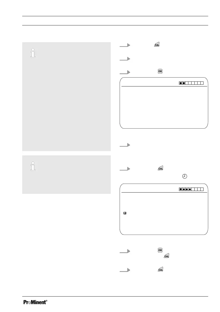
1.
Press the key in the continuous
display.
2. Using the arrow keys select
[Two point calibration]
3.
Then press
CAL F
-
Immerse sensor in buffer 1
Two point calibration
A1038
Sensor value 2.50 ppm
Sensor voltage 161.4 mV
Start with <CAL>
Fig. 51: Fluoride sensor calibration (CAL)
4. Immerse the sensor in test con‐
tainer 1 with calibration solution.
When doing so gently move the
sensor
5.
Then press
ð
[Calib. in progress]
.
CAL F
-
Two point calibration
A1040
Sensor value
2.50 ppm
Change with <OK>
continue with <CAL>
Fig. 52: Fluoride sensor calibration (CAL)
6.
Then press to change the ppm
value or press
to continue with
the calibration
7.
Then press
Calibration
81