9.3
Calibrating the Fluoride
Sensor
9.3.1
Selection of the calibration
process for fluoride
To calibrate the controller there are two
available calibration processes:
n 1 point
n 2 point
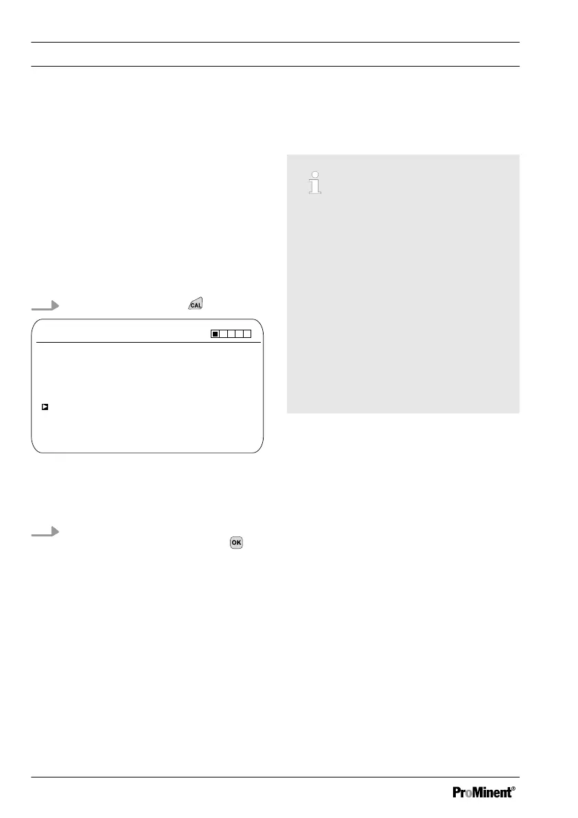
Calibration process selection
1.
Continuous display ➨
CAL F
-
A1037
-59.16 mV/dec
Slope
1 ppm = 185.0 mV 16:51:18
Single point calibration
11:11:11
11/11/2011
100 %
11/11/2011
Two point calibration
Fig. 50: Calibration menu [Fluoride]
ð
The calibration menu is dis‐
played.
2. Using the arrow keys select the
desired menu item. Press the
key
ð
You can now start the selected
calibration process.
9.3.2
2-point fluoride sensor cali‐
bration (CAL)
Correct sensor operation
–
Correct measuring and metering
is only possible if the sensor is
working perfectly
–
Observe the sensor operating
instructions
–
The carrying out of a 2-point cali‐
bration is strongly recommended
and is to be preferred to other
methods
–
For calibration the sensor must
be removed and refitted in the in-
line probe housing. To do this,
observe the operating instructions
of your in-line probe housing
Material required for calibration of fluoride
sensors:
n Two test containers with calibrating
solution
Calibration
80