Digital Demodulation
R&S
®
FPC
163User Manual 1178.4130.02 ─ 07
lation depth is the amount that the amplitude drops during the low state in %. The mod-
ulation depth is therefore a value < 100 %.
Another way to express the amplitude variations of an ASK modulated signal is the
modulation index. The expression comes from analog demodulation applications. The
R&S FPC shows the modulation as a numeric result in the diagram header.
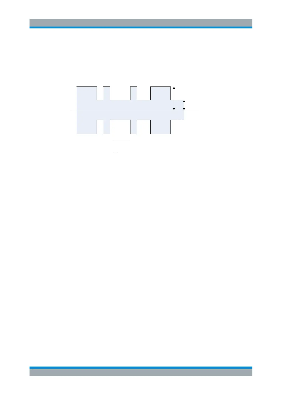
A (high amplitude)
B (low amplitude)
Modulation index =
(A – B)
(A + B)
Modulation depth =
B
A
Figure 17-7: Calculation of modulation index and depth
17.2 Measurement Configuration
Access: "Meas" > "Demod Parameters"
Access: "Setup" > "Config Overview" > "Bandwidth" (selected settings)
Remote commands required to define demodulation parameters:
●
Chapter 19.15.2, "Measurement Configuration", on page 318
A digital modulation system needs a transmit filter to limit the bandwidth of the trans-
mitted signal. The receiver needs to know the characteristics of that filter to be able to
demodulate the signal. Sometimes an additional receive filter is necessary for proper
demodulation. You also have to define other demodulation parameters like the symbol
rate or FSK deviation.
Other demodulation parameters like oversampling factor, reference filter or measure-
ment filter, are automatically selected by the R&S FPC.
Measurement Configuration