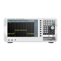
Instrument Tour
R&S
®
FPC
18User Manual 1178.4130.02 ─ 07
Power supply
The AC power supply and main power switch are located in a unit on the rear panel of
the instrument.
The main power switch has the following states.
●
Position "1": The instrument is supplied with power.
●
Position "0": The instrument is disconnected from the power supply.
Trigger input / external reference
This female BNC connector allows you to connect an external trigger signal or an
external reference signal.
When you are using the connector as a trigger input, you can trigger measurements
with an external trigger. For more information about triggered measurements, refer to
the user manual.
Alternatively, you can use the connector to connect a 10 MHz reference signal to syn-
chronize the frequency with the external reference. Note that the reference signal must
be stronger than 0 dBm.
LAN
The LAN interface allows you to connect the R&S FPC to a local network for remote
control, printouts or data transfer. The assignment of the RJ-45 connector supports
twisted-pair category 5 UTP/STP cables in a star configuration (UTP stands for
unshielded twisted pair, and STP for shielded twisted pair).
USB port (type B)
The USB port (type B) allows you to connect the R&S FPC to a computer and establish
a remote control connection.
Rear Panel

 Loading...