Preparing for use
R&S
®
NRPxxP
16User Manual 1179.5760.02 ─ 02
Setup
1
2
3
4
8
9
7
65
NRP
3-Path Diode Power Sensor
MHz to GHz, 100 pW to 200 mW (−70 dBm to +23 dBm)
SMART SENSOR TECHNOLOGY
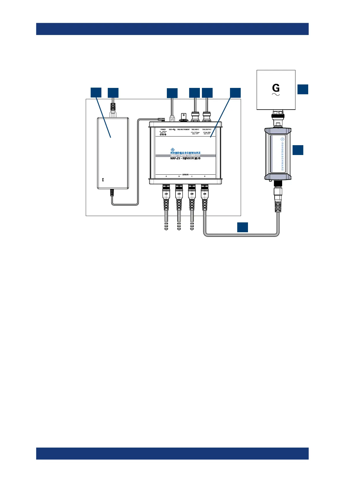
Figure 3-2: Setup with an R&S NRP-Z5 sensor hub
1 = External power supply unit
2 = Connect to AC power supply.
3 = Connect to computer with USB host interface.
4 = Optional: Connect to trigger source.
5 = Optional: Connect to triggered device.
6 = R&S NRP‑Z5 sensor hub
7 = Signal source (DUT)
8 = R&S NRPxxP power sensor
9 = R&S NRP‑ZK6 cable
Set up as shown in Figure 3-2.
1. Connect the R&S NRP‑ZK6 cable to the power sensor. See "To connect a cable to
the host interface of the power sensor" on page 13.
2. Connect the power sensors to the R&S NRP‑Z5 sensor hub. You can connect up to
four power sensors.
3. Connect the R&S NRP‑Z5 to the computer.
4.
NOTICE! Incorrectly connecting or disconnecting the power sensor can damage
the power sensor or lead to erroneous results. Ensure that you connect or discon-
nect the power sensor as described in Chapter 3.4, "Connecting to a DUT",
on page 12.
Connect the power sensors to the signal sources.
Connecting to a controlling host

 Loading...
