Operating concepts
R&S
®
NRPxxP
25User Manual 1179.5760.02 ─ 02
Setup
NRP
3-Path Diode Power Sensor
MHz to GHz, 100 pW to 200 mW (−70 dBm to +23 dBm)
SMART SENSOR TECHNOLOGY
1
2
3
4
5
6
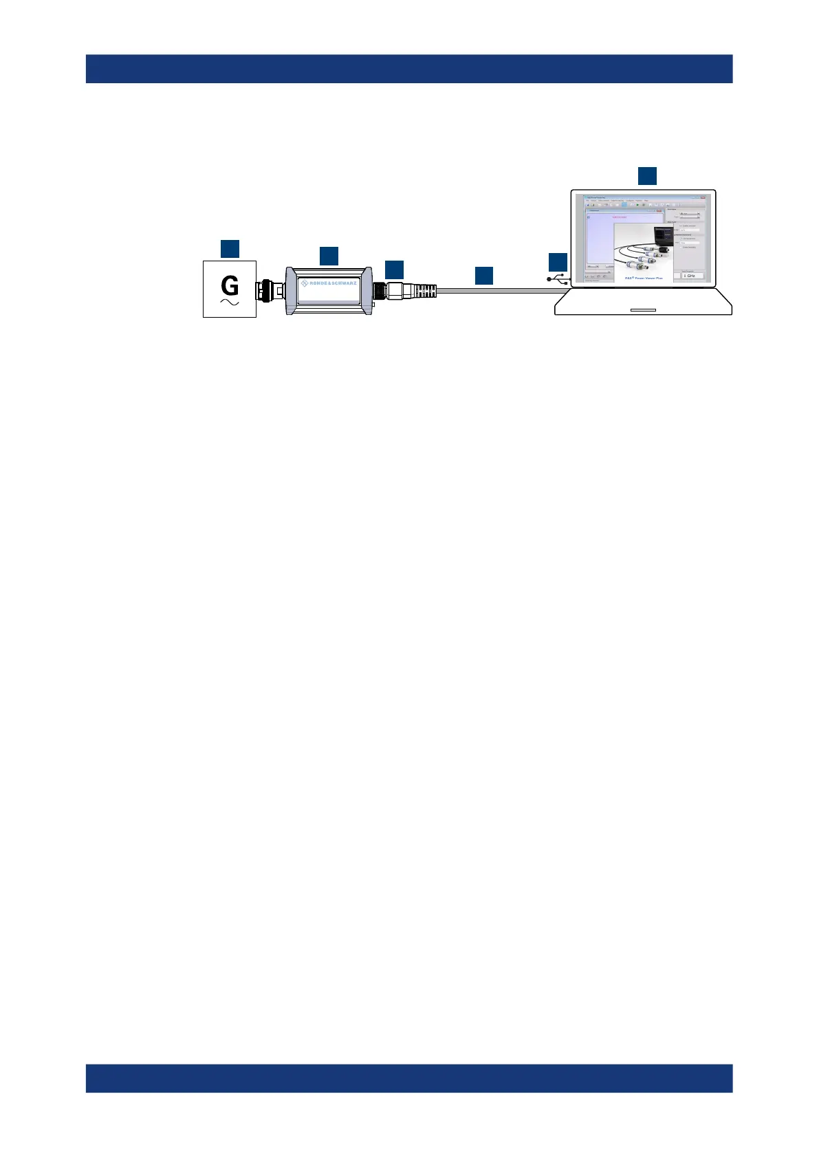
Figure 5-2: Setup with the R&S
Power Viewer
1 = Signal source
2 = R&S NRPxxP power sensor
3 = Host interface connector
4 = R&S NRP‑ZKU cable
5 = USB connector
6 = Computer with installed R&S Power Viewer
1.
NOTICE! Incorrectly connecting or disconnecting the power sensor can damage
the power sensor or lead to erroneous results. Ensure that you connect or discon-
nect the power sensor as described in Chapter 3.4, "Connecting to a DUT",
on page 12.
Connect the power sensor to the signal source.
2. Connect the cables as shown in Figure 5-2.
For a detailed description, refer to Chapter 3.7.1.1, "Simple USB connection",
on page 14.
Starting a measurement
For a detailed description, refer to the operating manual of the R&S Power Viewer. The
manual is installed automatically during the installation of the R&S Power Viewer.
1. Start the R&S Power Viewer.
2. Execute zeroing.
Note: Turn off all measurement power signals before zeroing. An active measure-
ment signal during zeroing causes an error.
3. Switch on the test signal of the signal source.
4. Select a measurement.
5. Start the measurement.
R&S
Power Viewer

 Loading...
