5.4 Installing the lifting column at the interfaces
5.4.1 Installing the internal profile - Multilift I/II
RK Rose+Krieger GmbH recommends that the lifting
column be fastened to the supporting/contact surface
on the motor side.
Personal:
n
Assembly staff
Schutzausrüstung:
n
Protective clothing
n
Protective gloves
n
Safety shoes
Prerequisite:
n The screwing surface on the connecting construction has been
prepared for fastening the lifting column.
1. Place the internal profile of the lifting column on the screwing
surface on the connecting construction, and position it.
The screwing surface on the connecting con-
struction must rest flat on the lifting column.
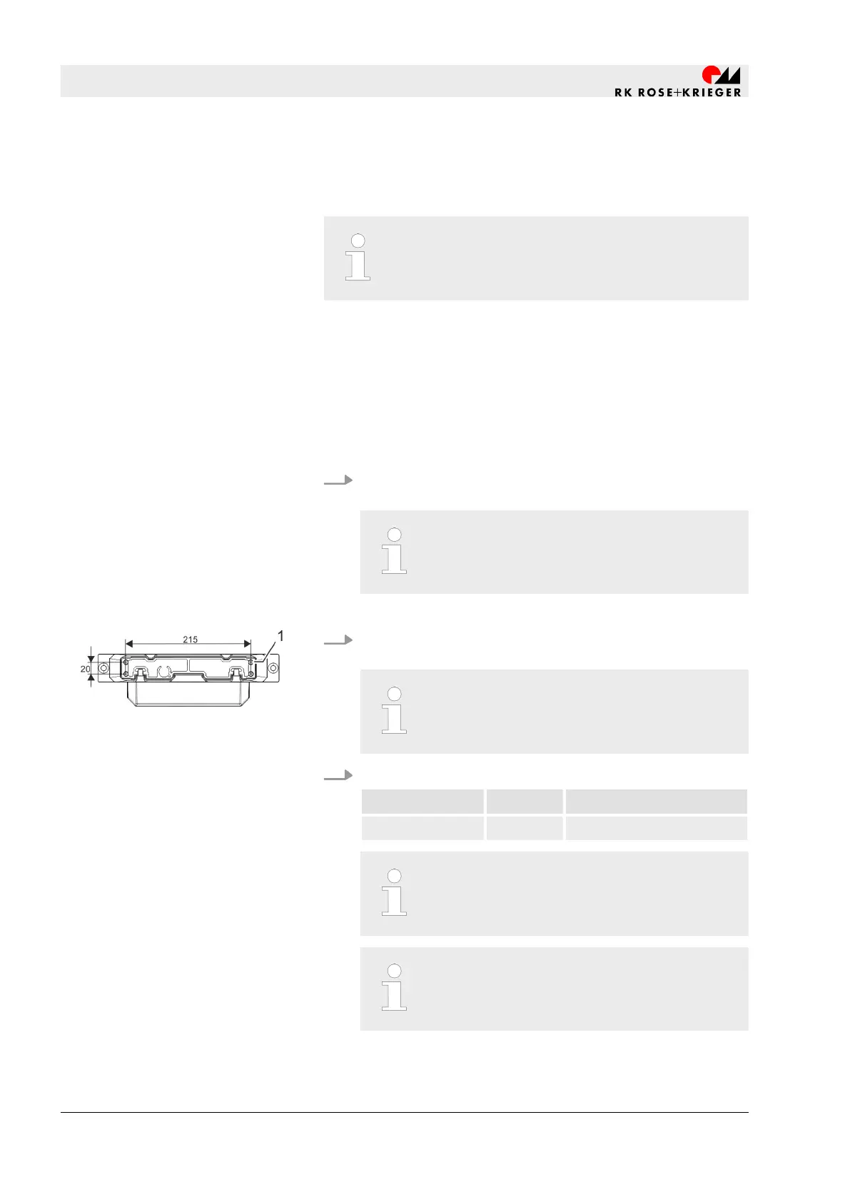
2. Insert 4 screws into the drilled holes (Fig. 28/1) on the con-
necting construction and lifting column.
The supporting surface of the lifting column must
rest fully on a metal plate of at least 5 mm in
thickness.
3. Tighten the screws alternating between them diagonally.
Screw size Strength Tightening torque [Nm]
M8 8.8 15
The minimum screw depth for initial installation is
20 mm, and 40 mm for repeated installation.
Use all the connection points of the Multilift for
the connecting constructions and options mod-
ules.
ð
The Multilift II lifting column has been fitted to the con-
necting construction.
Positioning the lifting column
Fastening the lifting column
Fig. 28: Connection points
-
Multilift
I/II
Assembly
Installing the lifting column at the interfaces > Installing the internal profile - Multilift I/II
20.02.2019Lifting column Multilift I/Multilift II104


 To Next Page