3.5.3 Electrical connection - Multilift II
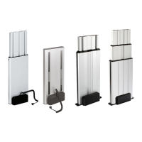
Fig. 19: Circuit diagram for Multilift II
A/B Output hall sensor
C Internal hall sensor in the motor
D Top limit switch
E Bottom limit switch
F Safety limit switch
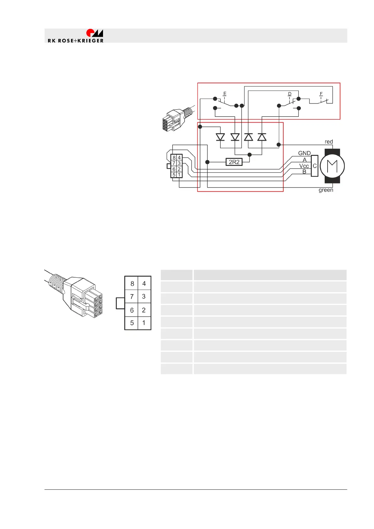
Pin Function
1 Motor +
2 N/A
3 +5 V
4 A
5 B
6 N/A
7 GND
8 Motor -
Hall sensor and wiring
Plug connector pin assignment
Fig. 20: Plug connector pin assign-
ment
Set-up and function
Electrical connection to a controller provided by the operator > Electrical connection - Multilift II
20.02.2019 Lifting column Multilift I/Multilift II 97