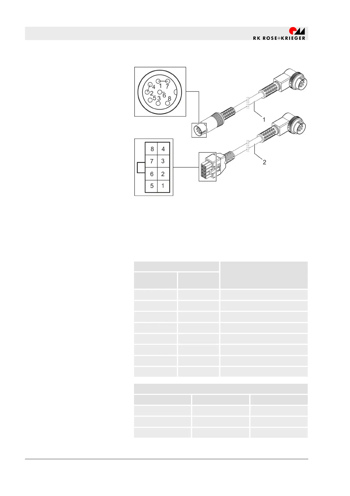
Fig. 18: Plug connector pin assignment
1 Adapter cable with 8-pin DIN plug connector
2 Adapter cable with Mini-Fit Jr. plug connector
The socket inlet on the motor housing of the Multilift I lifting column
can be connected to the controller provided by the operator with
two different adapter cables (Fig. 181 + 2).
Pin
Function
DIN plug con-
nector
Mini-Fit Jr.
1 + 7 1 Motor +
-
2 N/A
3 3 +5 V for hall sensor
6 4 Limit switch (internal)
8 5 Hall sensor pulse output
-
6 N/A
5 7 GND for hall sensor
2 + 4 8 Motor -
Current
Load [N] I [A] U [V DC]
0 1 24
1000 3 24
3000 4.5 24
Plug connector pin assignment
Set-up and function
Electrical connection to a controller provided by the operator > Electrical connection - Multilift I (Synchro)
20.02.2019Lifting column Multilift I/Multilift II96