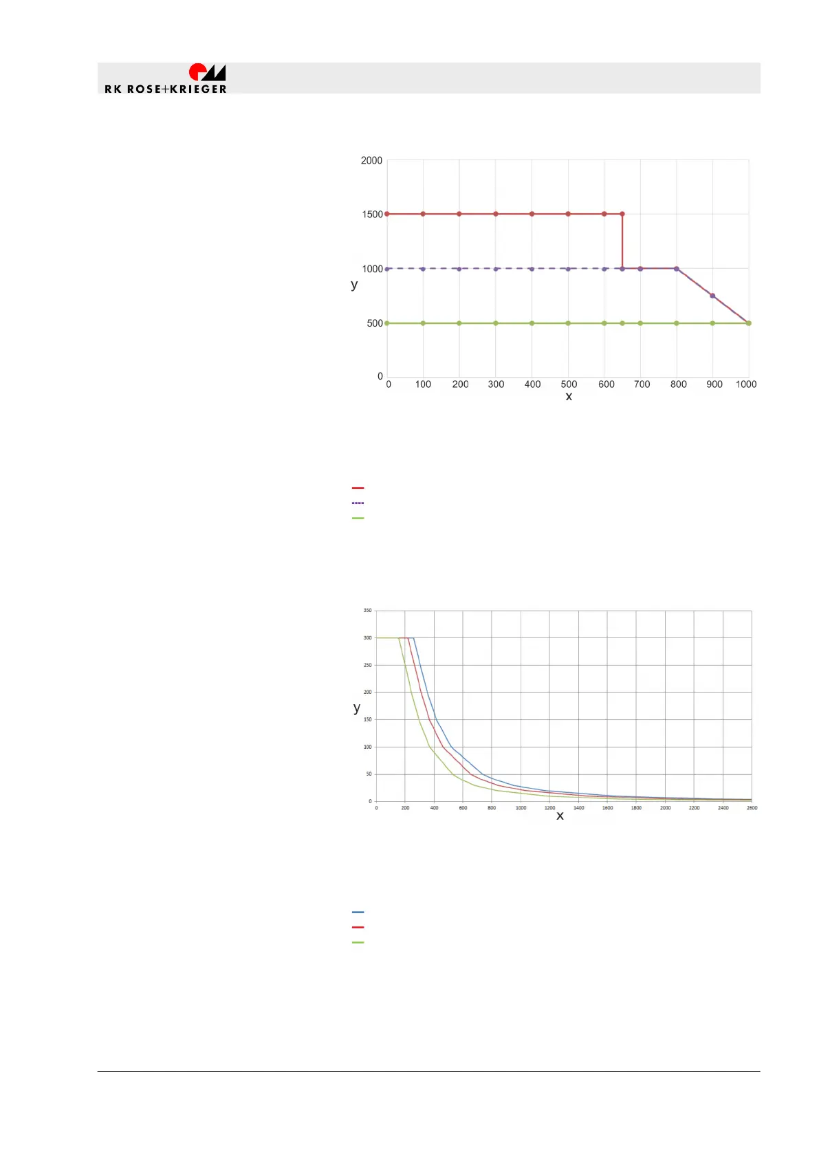
Fig. 36: Maximum compressive/tensile force depending on the
stroke length in medical applications
x Stroke [mm]
y F [N]
8 mm/s (compressive force)
16 mm/s (compressive force)
8/16 mm (tensile force)
8.3.3 Impulse diagram - Multilift II impact
Fig. 37: Permitted mass in relation to the settling velocity with dif-
ferent stroke lengths
x Settling velocity [mm/s]
y Mass [kg]
Stroke 355/400 mm
Stroke 450 mm
Stroke 500 mm
Maximum compressive/tensile
force depending on the stroke
length in medical applications
Permitted mass in relation to the
settling velocity with different
stroke lengths
Technical data
Diagrams > Impulse diagram - Multilift II impact
20.02.2019 Lifting column Multilift I/Multilift II 119


 To Next Page