54 Rockwell Automation Publication IASIMP-QS005H-EN-P - April 2016
Chapter 3 GuardLogix® Controllers Logic Integration
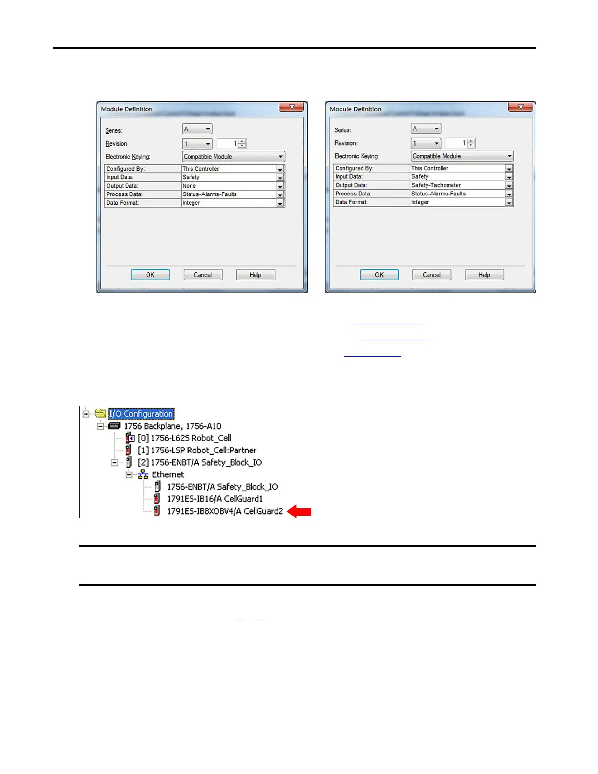
For analog I/O configuration settings, see the module definition examples below:
For more information on module definitions, refer to these manuals:
• Guard I/O DeviceNet Safety Modules User Manual, publication 1791DS-UM001
• Guard I/O EtherNet/IP Safety Modules User Manual, publication 1791ES-UM001
• POINT Guard I/O Safety Modules User Manual, publication 1734-UM013
9. Repeat these steps for all of the I/O modules in your application.
This example includes an additional module, a 1791ES-IB8XOBV4 module named CellGuard2.
10. Check your Safety Network Numbers (SNN).
The copy and paste module configuration procedure can create Guard I/O modules with the same SNNs on
different bridge modules. Follow steps 11
…15 to create a unique SNN for the Guard I/O modules on each
communication bridge module.
11. To change the SNN, right-click the Guard I/O module and choose Properties.
Analog Current and Voltage Only Modules Analog Tachometer, Current, and/or Voltage Module
IMPORTANT If you have more than one communication bridge module in your application, you must make sure that each subnet
that contains Guard I/O modules has a unique Safety Network Number (SNN).
 Loading...