3–24 Access Procedures
Publication 1336 IMPACT-6.8 – November, 2002
!
ATTENTION: Wear a wrist-type grounding strap
when servicing 1336 IMPACT drives. Failure to
protect drive components against ESD may damage
drive components. Refer to Electrostatic Discharge
Precautions at the beginning of this chapter.
1. Perform the following procedures found earlier in this chapter:
• Opening the Drive Enclosure
• Removing the Control Board Mounting Plate
• Removing the Precharge Board Mounting Frame
2. Remove the HV Guard that spans the bottom of the Inverter
Bay (held in place with hook-and-loop strips).
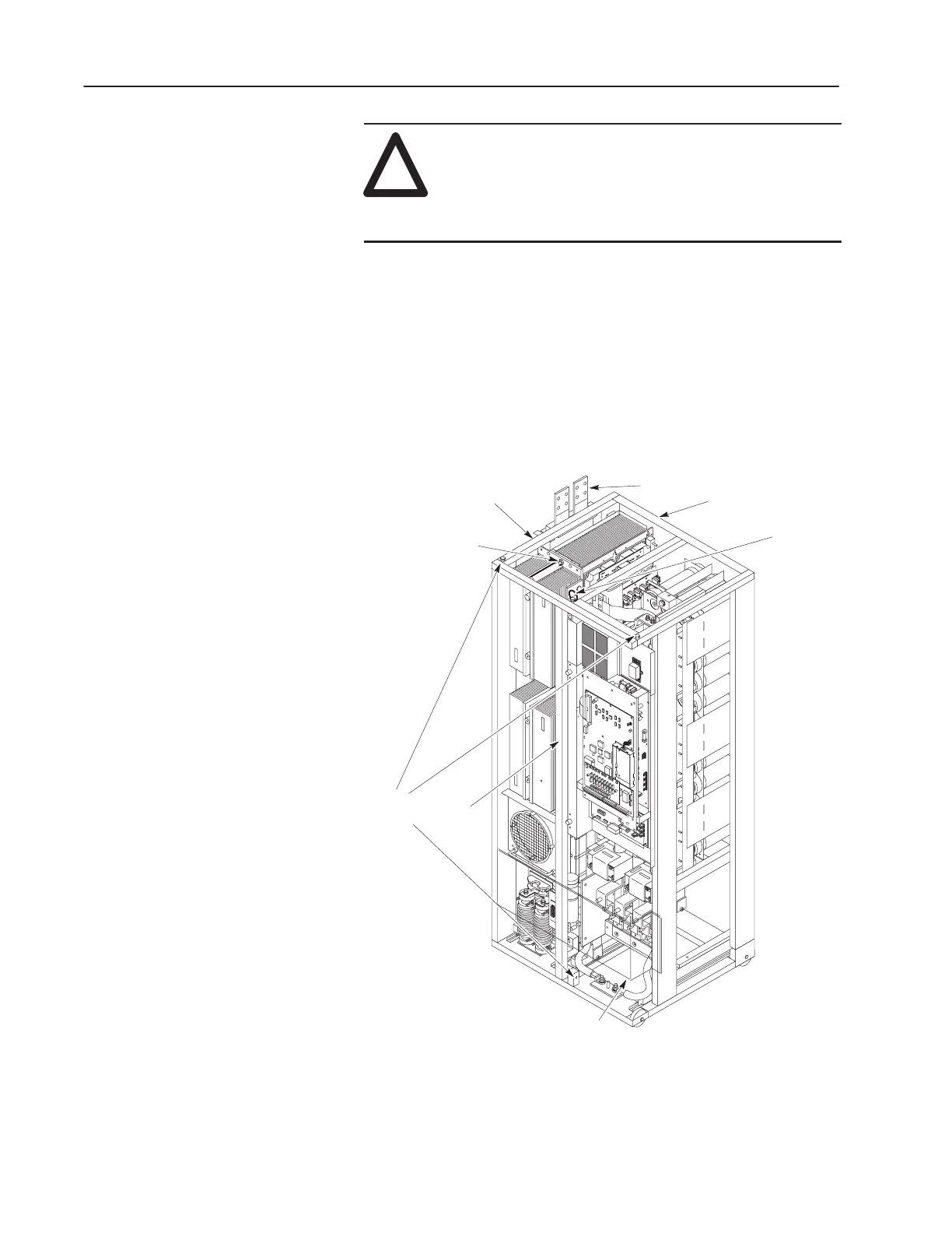
Figure 3.14
Access to the Inverter Assembly
AB0983A
Lock-Down Bolt
T Bar
Bolts
Snapper
Pin
T Bar
Inverter Assembly
Inverter Bay w/o Cabinet
DC Input Lines
HV Guard
3. Referring to Figure 3.14, disconnect the buses from the DC input
lines at the top left of the drive.
 Loading...


