3–25Access Procedures
Publication 1336 IMPACT-6.8 – November, 2002
Refer to Figure 3.14 and the following steps, to remove the T bar
from the front of the drive:
1. Loosen the lock-down bolt between the inverter and the left arm
of the T bar.
2. Remove the T bar mounting bolt at the bottom of the T bar.
3. Remove the bolts fastening each arm of the T bar.
4. Release the Snapper Pin at the top of the T bar.
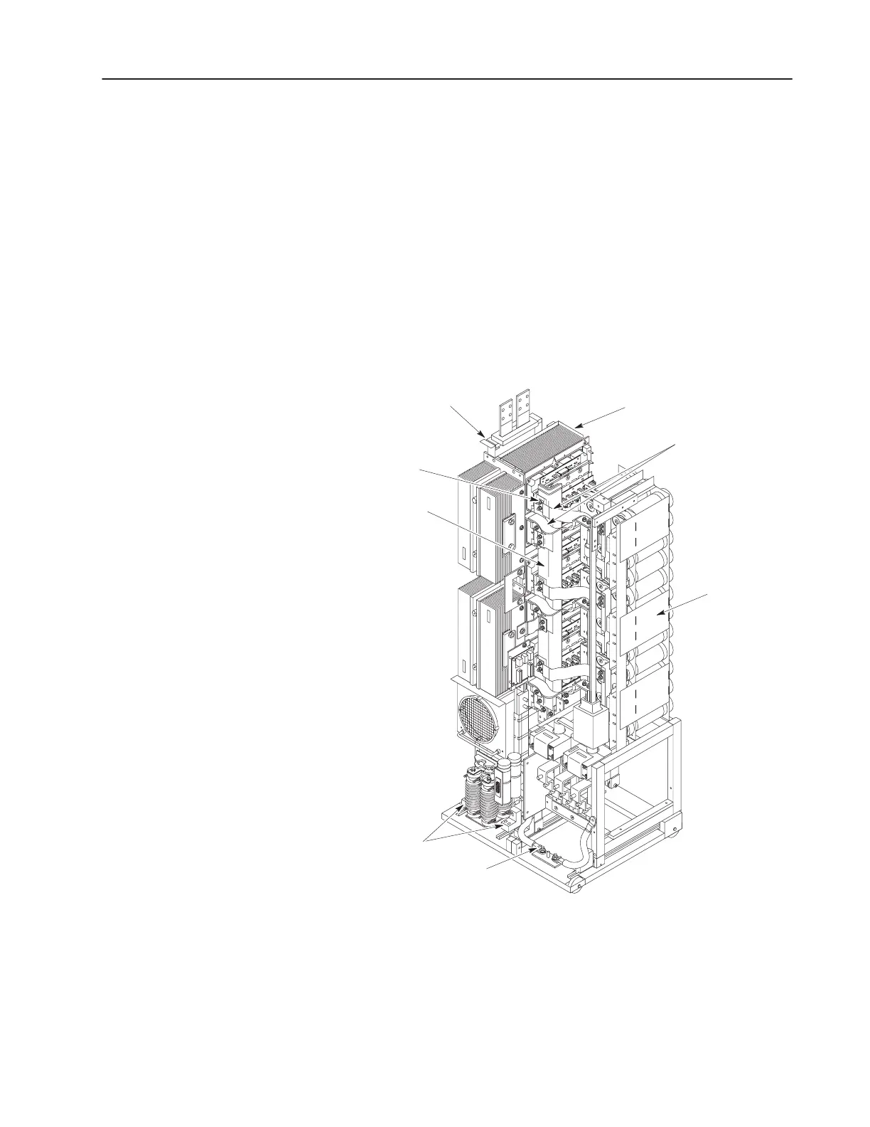
Refer to Figure 3.15 and the following steps, to remove connections
and the Spine:
Figure 3.15
Disconnecting the Spine
AB0984A
Flexible Bus Bars
Spine
Nuts (18)
Inverter Bay w/o Cabinet
Capacitor Bank
Assembly
Wheel
Chocks
Inverter Assembly
Ground Cable
Inverter Assembly
1. Remove the 18 nuts fastening the flexible buses to the Spine.
2. Pull all the flexible leads to the right, out of the way.
 Loading...


