32 Rockwell Automation Publication 2198-RM002A-EN-P - October 2017
Chapter 2 Servo Drive and System Comparison
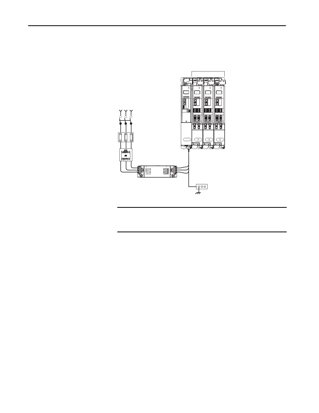
Kinetix 5700 servo drive systems have three-phase input power that is supplied
by a DC-bus (converter) power supply.
Figure 3 - Kinetix 5700 Configuration
MOD
NET
MOD
NET
2
1
2
1
1
I/O-A
6
510
1
I/O-B
6
510
1
I/O-A
61
I/O-B
6
510510
UFB-A UFB-B
UFB-A UFB-B
D+
D-
D+
D-
D+
D-
MF-A MF-B MF-A MF-B
D+
D-
MOD
NET
2
1
1
I/O-A
61
I/O-B
6
510510
UFB-A UFB-B
D+
D-
MF-B
D+
D-
MOD
NET
2
1
1
4
I/O
324…528V AC
Three-phase
Input Power
Bonded Cabinet
Ground Bus
2198-DB20-F
AC Line Filter
(required for CE)
Kinetix 5700 Drive System
(front view)
Bulletin 2198 shared-bus
connection system for
DC-bus and 24V DC control power.
Line Disconnect
Device
Circuit
Protection
Magnetic (M1)
Contactor
DC-bus
Power
Supply
Dual-axis Inverters
IMPORTANT Axis motoring and regeneration power requirement determines the size of
the DC-bus power supply, and the shunt and capacitance requirement. See
Motion Analyzer for sizing your Kinetix 5700 application.

 Loading...


