Rockwell Automation Publication 2198-RM002A-EN-P - October 2017 45
System Replacement Examples Chapter 3
Module Mounting Order
Kinetix 6000 drive modules (IAM, AM, shunt, and slot-filler) are mounted
according to power utilization (highest to lowest) from left to right starting
with the highest power utilization.
The Kinetix 5700 axis inverters are mounted according to power utilization
from left to right starting with the DC-bus power supply followed by the axis
inverter with the highest power utilization.
Power utilization is the average power (kW) consumed by a servo axis. If
Motion Analyzer was used to size the axis, the calculated axis power that is
required can be used for the power utilization value. If Motion Analyzer was
not used, you can use the continuous power value (kW) for each module to
determine mounting order.
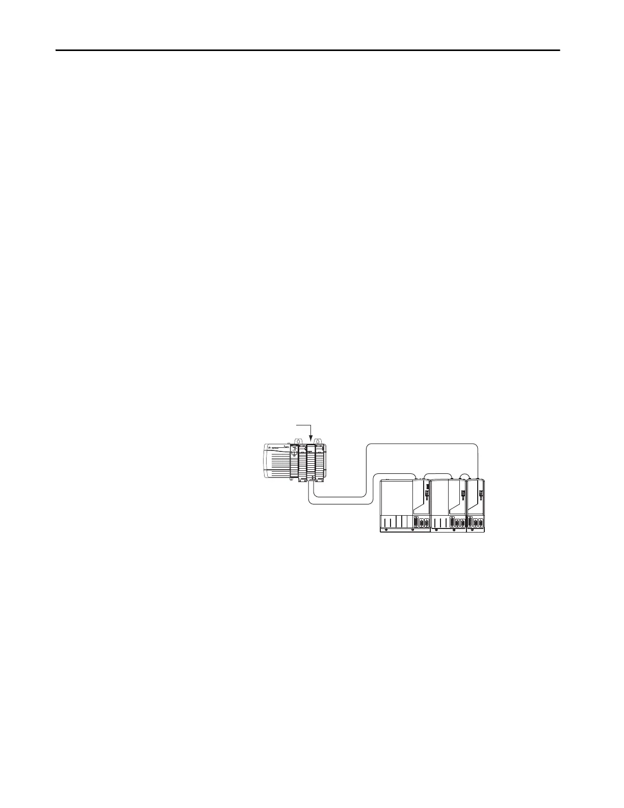
Kinetix 6000 Network Topology
The Kinetix 6000 servo drives use Sercos interface to communicate with the
LOGIX 5000™ controller and must be configured in ring topology. Sercos
fiber-optic cables connect between the drive and controller receive (Rx) and
transmit (Tx) connectors to form a Sercos fiber-optic ring.
Figure 10 - Sercos Fiber-optic Ring - LOGIX 5000 Controller with Double-wide Drive Modules
SERCOS interface
TM
Tx (rear)
Rx (front)
OK
CP
0.1 m
(5.1 in.)
0.2 m
(7.1 in.)
1756-M16SE Sercos
Interface Module
Sercos Fiber-optic Ring
Kinetix 6000 System
(5-axis power rail)
LOGIX 5000 Controller
(ControlLogix® controller is shown)

 Loading...


