56 Rockwell Automation Publication 2198-RM002A-EN-P - October 2017
Chapter 3 System Replacement Examples
Transformer Specifications
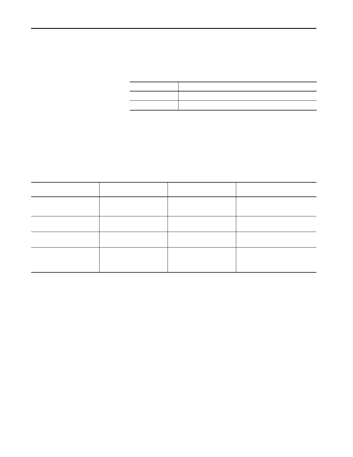
Follow these voltage requirements for sizing a system transformer.
Table 24 - Transformer Specifications
Shared-bus Connections
Use the following shared-bus connector kits with your Kinetix 5700 drive
system.
Table 25 - Shared-bus Connector Kits
Drive Cat. No. Specifications
(1)
(1) An isolation transformer for three-phase input power is not required for the Kinetix 6000 IAM or Kinetix 5700 DC-bus supply.
2094-BC07-M05-S 45 kW continuous x 1.5 = 67.5 KVA
2198-P141 31 kW continuous x 1.5 = 46.5 KVA
Shared-bus Connector Kit
Cat. No.
Drive Module
Cat. No.
Application Description
2198-TCON-24VDCIN36
2198-BARCON-xxDCAC100
2198-P141 24V DC input power to control bus
24V input wiring connectors and bus-bars for
the Kinetix 5700 drive system 24V shared-bus
connection system (optional).
2198-H040-P-T
2198-D012-ERS3
2198-D020-ERS3
Control power sharing
Control power T-connector with bus bars,
55 mm
2198-H070-P-T
2198-D057-ERS3
2198-S086-ERS3
Control power sharing
Control power T-connector with bus bars,
85 mm
2198-BARCON-xxDC200
2198-KITCON-ENDCAP200
2198-Dxxx-ERS3
2198-Sxxx-ERS3
Shared-bus connector kits
DC-bus links (55, 85, and 100 mm) and end caps
for the DC-bus shared-bus connection system
(required and included with each respective
drive module).

 Loading...


