Rockwell Automation Publication 2198-RM002A-EN-P - October 2017 41
Servo Drive and System Comparison Chapter 2
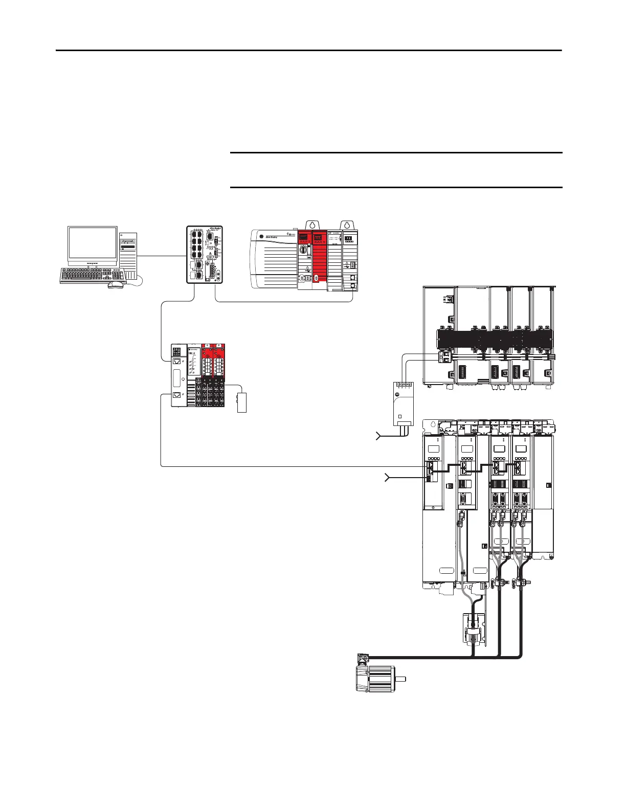
Kinetix 5700 Servo Drive System Example
This example control system uses a single GuardLogix® 5570 safety controller,
and a DC common-bus configuration of the Kinetix 5700 drive system with
Motion and Safety connections.
Figure 6 - Motion and Safety Configuration (single controller)
IMPORTANT Other configuration options are available that do not require a safety
controller.
1606-XL
Power Supply
Input
Allen-Bradley
LNK1LNK2 NET OK
EtherNet/IP
1
2
MOD
NET
MOD
NET
MOD
NET
MOD
NET
2
1
1
1
4
I/O
I/O
6
5
10
2
1
2
1
2
1
1
I/O-A
6
510
1
I/O-B
6
510
1
I/O-A
61
I/O-B
6
510510
UFB
UFB-A UFB-B
UFB-A UFB-B
D+
D-
D+
D-
D+
D-
MF-A MF-B MF-A MF-B
D+
D-
MBRK
+
-
SB+/NC
S1A
SCA
S2A
SB-
NC
NC
NC
1
8
SB+/NC
S1A
SCA
S2A
SB-
S1B
SCB
S2B
SB+/NC
S1A
SCA
S2A
SB-
S1B
SCB
S2B
1
8
1
8
DC+
SH
9
16
9
16
9
16
1585J-M8CBJM-x
Ethernet (shielded) Cable
Compact GuardLogix 5370 or
GuardLogix 5570 Safety Controller
(GuardLogix 5570 Safety Controller is shown)
Studio 5000
Logix Designer Application
(version 26.00 or later)
AC Input Power
Kinetix 5700 Servo Drive System
(top view)
Kinetix 5700 Servo Drive System
(front view)
Digital Inputs to Sensors and Control String
1606-XLxxx Power Supply
for 24V DC Control, Digital Inputs,
and Motor Brake Power
Compatible Motors and Actuators
(Kinetix VP servo motor is shown)
1783-BMS
Stratix® 5700
Switch
Module Definition
Configured with
Motion and Safety
Connection
1734-AENTR
POINT Guard I/O™
EtherNet/IP™ Adapter
Safety
Device

 Loading...


