Rockwell Automation Publication 750-TG100B-EN-P - June 2019 115
Frame 7 Components Chapter 6
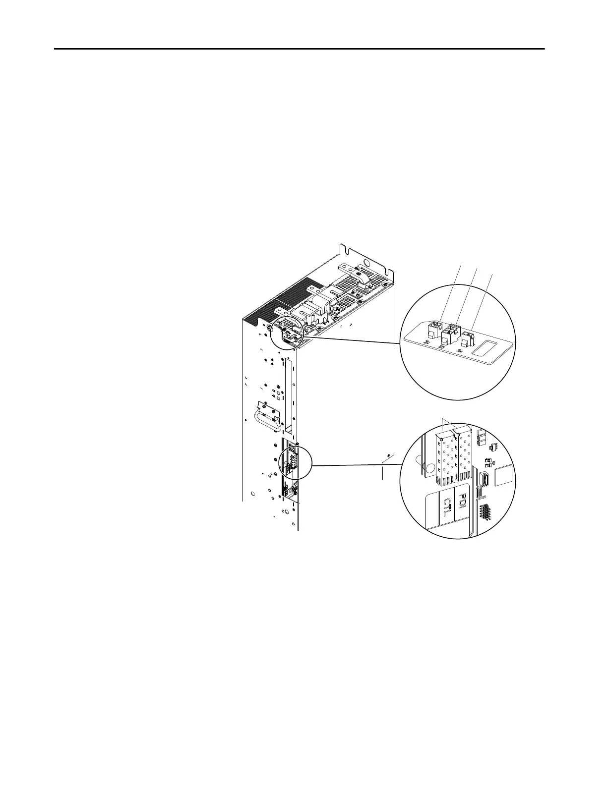
7. Without bending the cable to a radius less than 50 mm (2 in.), remove the
fiber-optic cables from the transceiver in the CTL and PDI (if present)
ports on the power interface circuit board and remove the fiber-optic
cables from the power module chassis.
8. For line side converter power modules, disconnect the DC fuse wire
harness connector P1 from connector J1 on the I/O panel on the power
module.
9. For line side converter power modules, disconnect the 24V DC signal wire
harness connector P3 from J3 on the I/O panel on the power module.
10. Disconnect the 240V AC and optional 24V DC power supply wire
harness connector P4 from J4 on the I/O panel on the power module.

 Loading...


