EasyManuals Logo

Rockwell Automation Allen-Bradley PowerFlex 750 Series Service Manual

Rockwell Automation Allen-Bradley PowerFlex 750 Series
352 pages
To Next Page IconTo Next Page
To Previous Page IconTo Previous Page
Page #116 background imageLoading...
Page #116 background image
116 Rockwell Automation Publication 750-TG100B-EN-P - June 2019
Chapter 6 Frame 7 Components
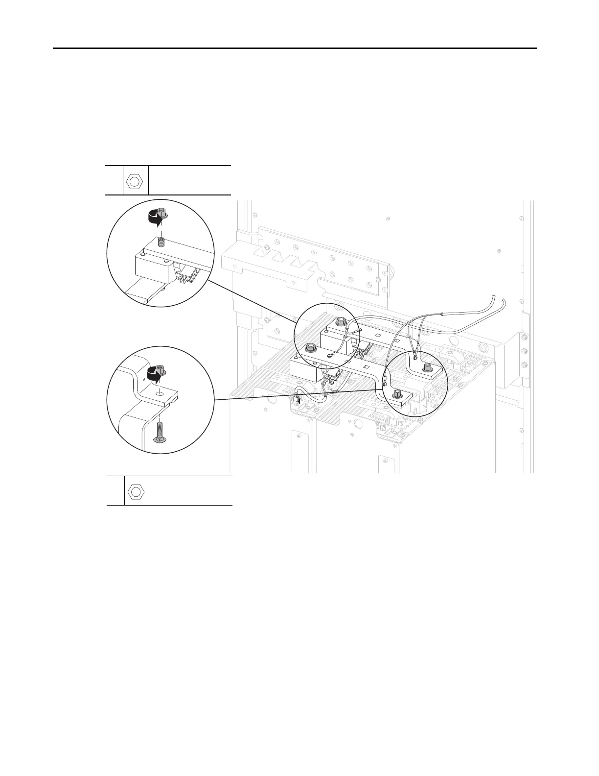
11. Remove the two M12 nuts that secure the top of the DC fuses to the DC
bus terminals on the line side converter power module. For bus supplies,
remove the DC link/fuses.
12. For drives only, remove the two M10 nuts that secure the DC link bus bars
to the DC terminals on the motor side converter power module and
remove the DC link/fuse assembly.
11
M12
19 mm
45 N•m (398 lb•in)
12
M10
17 mm
37.9 N•m (336 lb•in)
Regenerative Drive Configuration Shown.
11
12
LCL Filter Module Not Shown
for Clarity Only

Table of Contents

Other manuals for Rockwell Automation Allen-Bradley PowerFlex 750 Series

Questions and Answers:

Question and Answer IconNeed help?

Do you have a question about the Rockwell Automation Allen-Bradley PowerFlex 750 Series and is the answer not in the manual?

Rockwell Automation Allen-Bradley PowerFlex 750 Series Specifications

General IconGeneral
BrandRockwell Automation
ModelAllen-Bradley PowerFlex 750 Series
CategoryDC Drives
LanguageEnglish

Related product manuals