EasyManuals Logo

Rockwell Automation Allen-Bradley PowerFlex 750 Series Service Manual

Rockwell Automation Allen-Bradley PowerFlex 750 Series
352 pages
To Next Page IconTo Next Page
To Previous Page IconTo Previous Page
Page #160 background imageLoading...
Page #160 background image
160 Rockwell Automation Publication 750-TG100B-EN-P - June 2019
Chapter 7 Control Bay and Control Pod Components
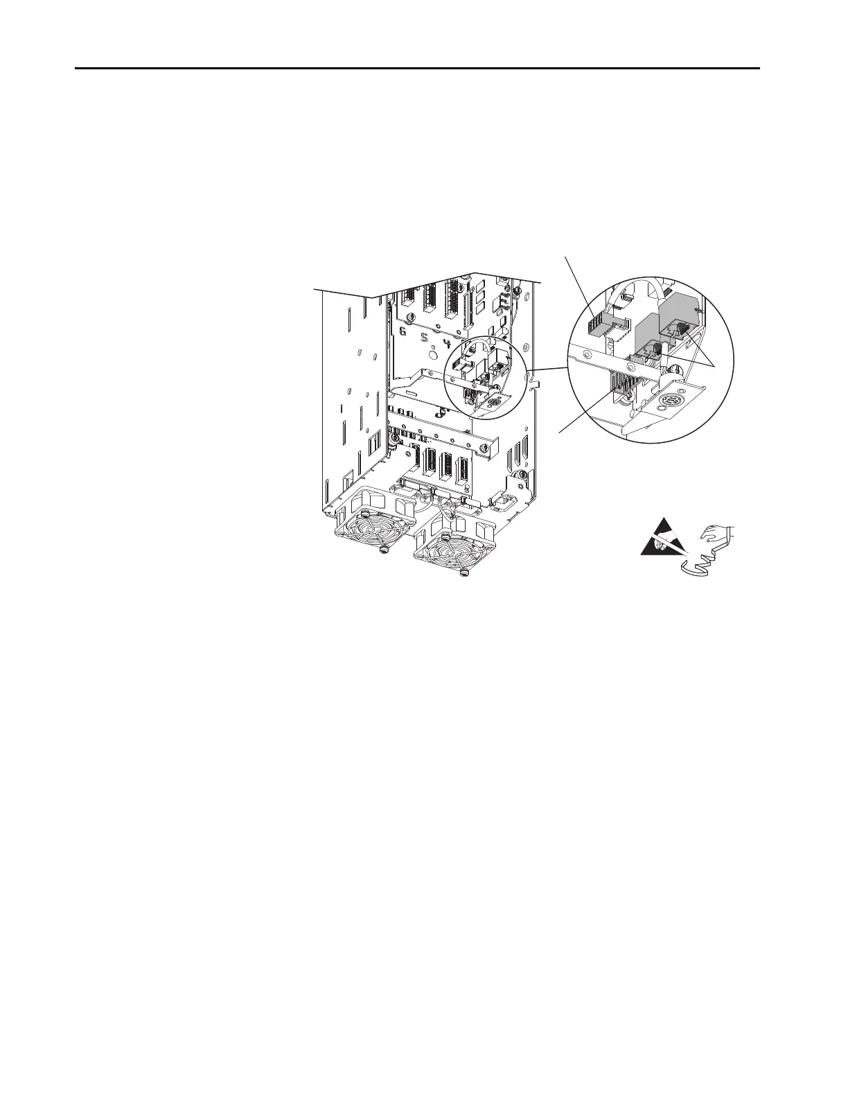
14. Disconnect the HIM plug-in terminal block for the mini-DIN connector
on the control board.
15. Disconnect any Ethernet cables from the ports on the bottom of the main
control board.
16. Disconnect the plug-in terminal block (TB1) on the bottom of the main
control board.
17. If installed, disconnect all option module plug-in terminal blocks.
18. If installed, remove the option module in slot 7, by loosening the two
captive thumb screws on the module and by pulling the board out of the
control pod. The tightening torque for installation is the same as for the
main control board.
14
15
16
=

Table of Contents

Other manuals for Rockwell Automation Allen-Bradley PowerFlex 750 Series

Questions and Answers:

Question and Answer IconNeed help?

Do you have a question about the Rockwell Automation Allen-Bradley PowerFlex 750 Series and is the answer not in the manual?

Rockwell Automation Allen-Bradley PowerFlex 750 Series Specifications

General IconGeneral
BrandRockwell Automation
ModelAllen-Bradley PowerFlex 750 Series
CategoryDC Drives
LanguageEnglish

Related product manuals