45 / 291 - EN -
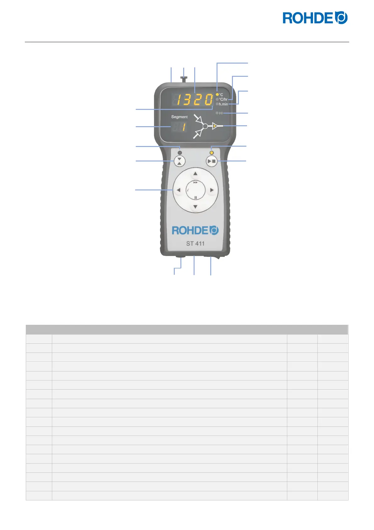
2.3. Control unit overview
No. Description ST 410 ST 411
1
USB port
X X
2
“USB flash drive plugged into USB port” indicator
X X
3
Main display
X X
4
“Temperature” indicator
X X
5
“Ramp rate” indicator
X X
6
“Time” indicator
X X
7
“Kiln heating” indicator
X X
8
“Data transfer” indicator
X X
9
Segment display
X X
10
Graphical program operation display
X X
11
“Program running” indicator
X X
12
Start/stop key
X X
13
Switch output (event) indicator
− X
14
Switch output key (event)
− X
15
Control keys (including the “INFO key [ i ]”)
X X
16
Fuse
X X
17
Cable with CPC 14 connector (connection to the kiln)
X X
18
Mains switch
X X
10
11
1
2
4
5
6
7
8
3
9
12
13
14
15
16
17
18
 Loading...
