Do you have a question about the Rohde ST 310 and is the answer not in the manual?
Introduces the ST 310 controller and its purpose in kiln operation.
Lists the parts included with the ST 310 control system package.
Details the key functionalities and capabilities of the ST 310 controller.
Provides technical specifications such as protection class, IP rating, and supply.
Outlines the Wi-Fi standards, security protocols, and bit rate supported by the controller.
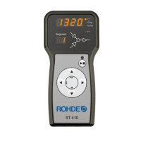
Identifies and describes the physical components and indicators of the control unit.
Details the numbered parts and their functions on the ST 310 control unit.
Explains the different segments of a firing curve program structure.
Describes the 14-pin connector used for connecting the control unit to the kiln.
Details the function of each pin in the 14-pin CPC connector.
Explains the necessity and method for suppressing kiln contactors with a varistor.
General advice on following safety instructions for the control unit and kiln.
Provides critical safety warnings and precautions regarding operation and potential hazards.
Safety advice specific to the placement and mounting of the control unit.
Instructions on how to attach the mounting bracket for the control unit.
Step-by-step guide on how to connect the cable between the control unit and the kiln.
Information regarding optional extension cables and EMC considerations.
Warning about potential damage if kiln/controller wiring mismatches.
Basic operational principles and functions of the control unit.
Instructions for powering the control unit on and off using the selector switch.
Explains how to lock and unlock the control unit's keys to prevent accidental changes.
A simplified guide to calling up, starting, ending, and changing firing programs.
Instructions for setting the internal clock of the controller.
Describes the functionality of the INFO key for accessing program information.
Explains the various display screens shown after the controller is powered on.
Details the sequence of displays after power-up, including software version.
Explains the indicator for the kiln heating status.
Lists and describes four pre-programmed firing cycles for ceramics.
Provides general guidance on using and customizing firing programs.
Details the steps involved in a typical firing program sequence.
Step-by-step instructions for selecting and modifying firing programs.
Explains how to use 'FULL' and 'END' options for ramp rates in firing programs.
Instructions on how to initiate and terminate a firing process using the key.
Advice on checking program values and handling kiln temperature deviations.
Details program delay and advance functions for controlling firing start and progression.
General guide to operating the firing process using the controller.
How to start, end, and restart a firing process with the key.
How to halt and restart the kiln using the key, cautioning against misuse.
Instructions on setting a delayed start time for the firing program.
How to manually advance the firing program by one step.
How to pause the firing program, including safety warnings about prolonged soaking.
Guidance on operating the controller during firing processes.
How to modify firing parameters while a program is running.
Explains controller behavior when kiln performance lags behind programmed rates.
How to check energy consumption and kiln performance data.
Describes how the controller handles power interruptions during firing.
Notes that programs and data are saved when the controller is turned off.
Explains that errors trigger a buzzer and display messages, terminating the firing.
Notes that error messages alternate with the kiln temperature display.
How to get more information about an error, like max temperature or duration.
Lists specific error codes, their descriptions, and causes/troubleshooting steps.
Explains the "program error" message and how to clear and restart.
Introduces the Wi-Fi module for wireless connection and app usage.
Overview of Wi-Fi capabilities, remote monitoring, and program transfer.
Explains the indicator light for wireless data transmission.
Lists supported Wi-Fi standards, security protocols, and connection points.
Step-by-step guide for connecting the controller to a Wi-Fi network using WPS.
Instructions for manual Wi-Fi connection without WPS.
Overview of the myKiln app for data visualization, archiving, and program management.
Instructions on how to register the controller using its unique access code.
Prohibition on connecting devices other than USB flash drives to the port.
Explains the USB port's function for data logging and file transfer.
Details USB version compatibility, formatting, and tested capacities.
Step-by-step guide on handling USB flash drives in the port.
Explains the indicator light for USB data transfer.
Notes on the integrated real-time clock for data logging timestamps.
Details on data logging process, file naming, and storage limitations.
How to set the interval for data logging.
Describes the structure and content of the log files generated.
Recommendation to regularly transfer files from the USB drive.
Introduction to ROHDEgraph software for visualizing and archiving firing curves.
Explains the meaning of status codes used in ROHDEgraph log files.
Safety warnings for troubleshooting and repair work on the unit.
Lists common faults like unit not switching on and error messages.
Step-by-step guide for replacing the fuse in the control unit.
Explains how parameters can be adjusted to suit user requirements.
Lists key parameters like kiln output and logging interval with their settings.
Detailed steps for modifying configurable parameters on the control unit.
Safety precautions to avoid damage when cleaning the control unit.
Specific instructions for cleaning the control unit using a dry cloth.
Details about the warranty period and exclusions.
Notes on deviations, technical changes, and intellectual property.
| Brand | Rohde |
|---|---|
| Model | ST 310 |
| Category | Control Unit |
| Language | English |